Disassembly


DISASSEMBLY
1. INSTALL ENGINE TO ENGINE STAND FOR DISASSEMBLY
2. REMOVE TIMING CHAIN
3. REMOVE CYLINDER HEAD
4. REMOVE KNOCK SENSOR
5. REMOVE ENGINE WIRE CLAMPS
6. REMOVE PLUG
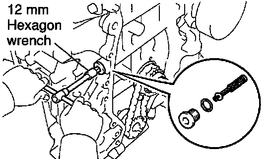
7. REMOVE OCV FILTER
Using a 12 mm hexagon wrench, remove the plug, gasket and OCV filter.
8. REMOVE WATER PUMP
9. REMOVE THERMOSTAT
10. REMOVE ENGINE COOLANT DRAIN UNION

11. REMOVE OIL DIPSTICK AND GUIDE
a Remove the bolt, oil dipstick and guide.
b Remove the O-ring from the oil dipstick.

12. REMOVE WATER BYPASS PIPE
Remove the 2 nuts, bolt, water bypass pipe and gasket.
13. REMOVE OIL PUMP
14. REMOVE OIL FILTER

15. REMOVE OIL FILTER UNION
Using a 12 mm hexagon wrench, remove the oil filter union.
16. REMOVE CRANK CASE
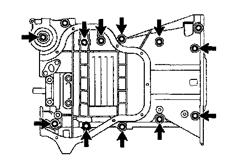
a Uniformly loosen and remove the 11 bolts in several passes, in the sequence shown.
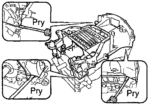
b Using a screwdriver, remove the crank case by prying the portions between the crank case and cylinder block.
NOTICE: Be careful not to damage the contact surfaces of the crankcase and cylinder block.
c Remove the O-ring.
17. REMOVE CRANKSHAFT REAR OIL SEAL
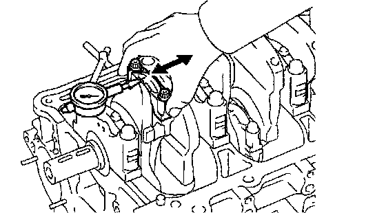
18. CHECK CONNECTING ROD THRUST CLEARANCE
Using a dial indicator, measure the thrust clearance while moving the connecting rod back and forth.
Standard thrust clearance: 0.160 - 0.362 mm (0.0063 - 0.0143 inch)
Maximum thrust clearance: 0.362 mm (0.0143 inch)
If the thrust clearance is greater than maximum, replace the connecting rod assembly. If necessary, replace the crankshaft.
Connecting rod thickness: 19.788 - 19.840 mm (0.7791 - 0.7811 inch)
19. REMOVE CONNECTING ROD CAPS AND CHECK OIL CLEARANCE
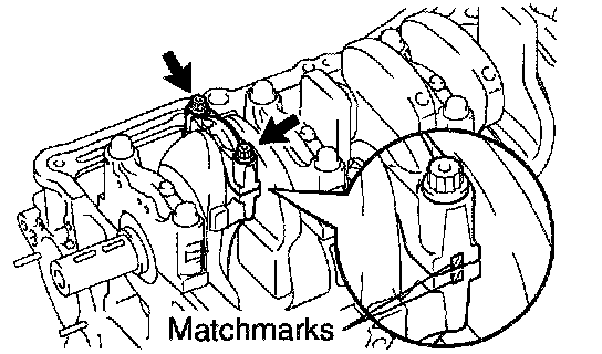
a Check the matchmarks on the connecting rod and cap are aligned to ensure correct reassembly.
b Remove the 2 connecting rod cap bolts.
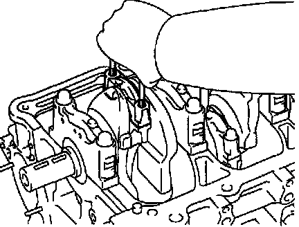
c Using the 2 removed connecting rod cap bolts, remove the connecting rod cap and lower bearing by wiggling the connecting rod cap right and left.
HINT: Keep the lower bearing inserted with the connecting rod cap.
d Clean the crank pin and bearing.
e Check the crank pin and bearing for pitting and scratches. If the crank pin or bearing is damaged, replace the bearings. If necessary, replace the crankshaft.
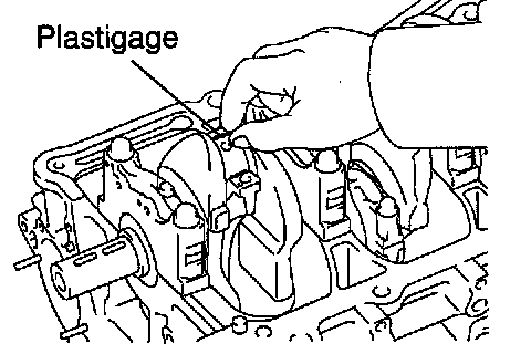
f Lay a strip of Plastigage on the crank pin.

g Install the connecting rod cap.
NOTICE: Do not turn the crankshaft.
h Remove the connecting rod cap (See procedure b and c).
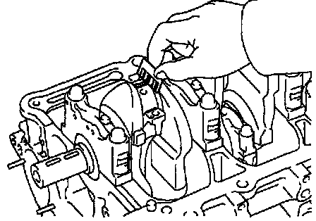
i Measure the Plastigage at its widest point.
Standard oil clearance: 0.024 - 0.048 mm (0.0009 - 0.0019 inch)
Maximum oil clearance: 0.08 mm (0.0031 inch)
If the oil clearance is greater than maximum, replace the bearings. If necessary, replace the crankshaft.
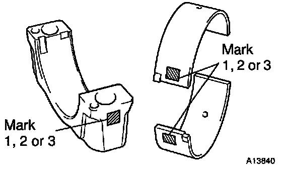
HINT: If replacing a bearing, replace it with one having the same number as marked on the connecting rod. There are 3 sizes of standard bearings, marked "1", "2" and "3" accordingly.
Reference
Standard bearing center wall thickness
j Completely remove the Plastigage.

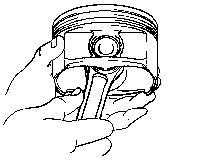
20. REMOVE PISTON AND CONNECTING ROD ASSEMBLIES
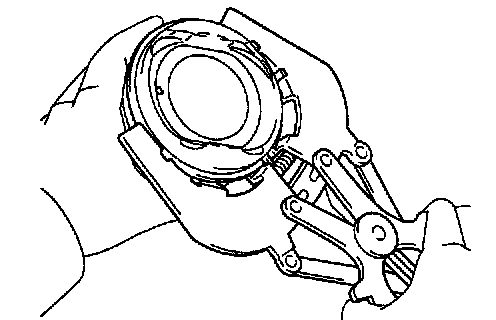
a Using a ridge reamer, remove all the carbon from the top of the cylinder.
b Push the piston, connecting rod assembly and upper bearing through the top of the cylinder block.
HINT:
- Keep the bearings, connecting rod and cap together.
- Arrange the piston and connecting rod assemblies in the correct order.
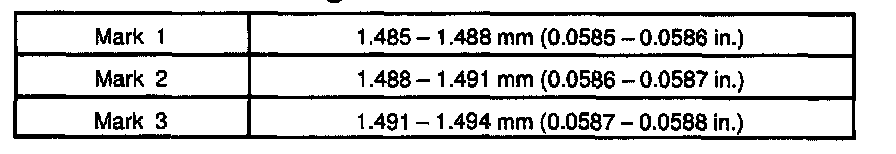
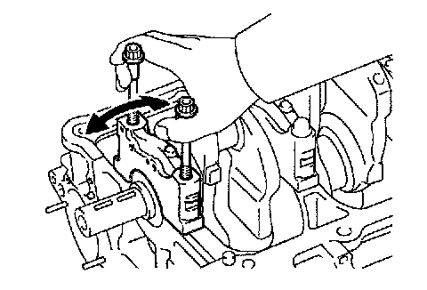
21. CHECK CRANKSHAFT THRUST CLEARANCE
Using a dial indicator, measure the thrust clearance while prying the crankshaft back and forth with a screwdriver.
Standard thrust clearance: 0.040 - 0.240 mm (0.0016 - 0.0094 inch)
Maximum thrust clearance: 0.30 mm (0.0118 inch)
If the thrust clearance is greater than maximum, replace the thrust washers as a set.
Thrust washer thickness: 1.930 - 1.980 mm (0.0760 - 0.0780 inch)
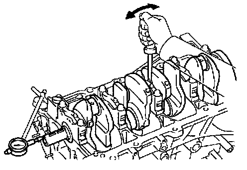
22. REMOVE MAIN BEARING CAPS AND CHECK OIL CLEARANCE
Main Bearing Cap Bolt Removal Sequence:
a Uniformly loosen and remove the 10 main bearing cap bolts in several passes, in the sequence shown.
b Using the 2 removed main bearing cap bolts, remove the 5 main bearing caps and 5 lower bearings.
NOTICE: Be careful not to damage the cylinder block.
HINT:
- Keep the lower bearing and main bearing cap together.
- Arrange the main bearing caps in the correct order.
c Lift out the crankshaft.
HINT: Keep the main bearings and thrust washers together with the cylinder block.
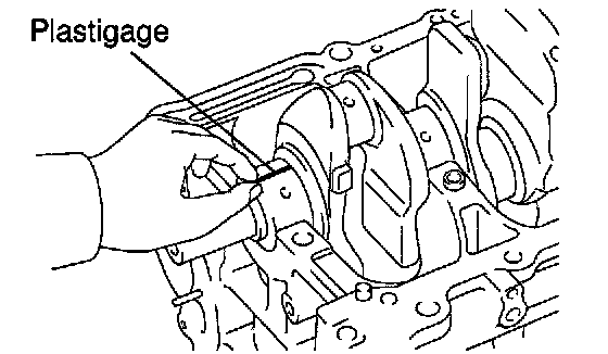
d Place the crankshaft on the cylinder block.
e Lay a strip of Plastigage across each journal.
Main Bearing Cap Bolt Torque Sequence:

f Install the main bearing caps.
NOTICE: Do not turn the crankshaft.
g Remove the main bearing cap (See procedure a and b).
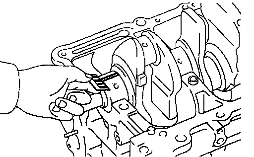
h Measure the Plastigage at its widest point.
Standard on clearance: 0.017 - 0.040 mm (0.0007 - 0.0016 inch)
Maximum oil clearance: 0.050 mm (0.0020 inch)
If the oil clearance is greater than maximum, replace the bearings. If necessary, replace the crankshaft.
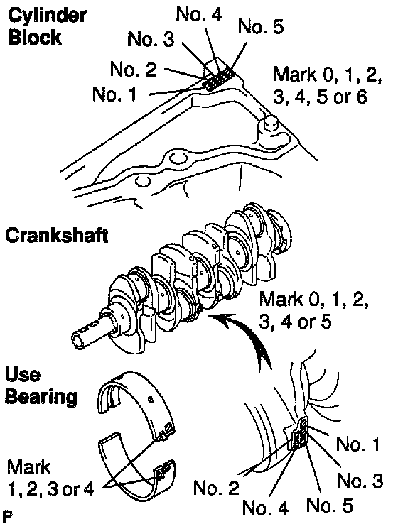
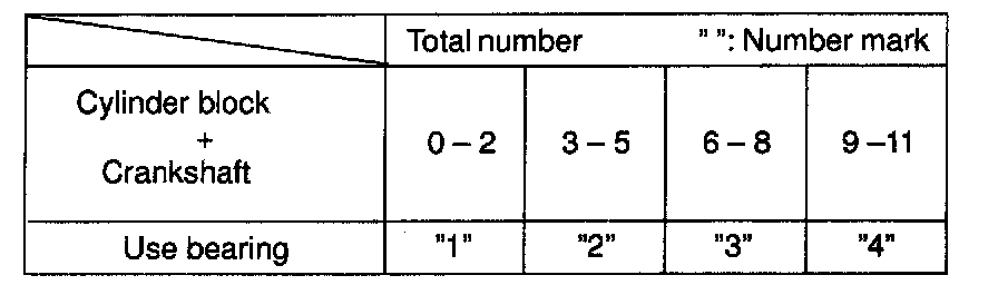
i If using a standard bearing, replace it with one having the same number. If the number of the bearing cannot be determined, select the correct bearing by adding together the numbers imprinted on the cylinder block and crankshaft, then selecting the bearing with the same number as the total. There are 4 sizes of standard bearings, marked "1", "2" "3" and "4" accordingly.
EXAMPLE: Cylinder block "4" + Crankshaft "3" = Total number 7 (Use bearing "3")
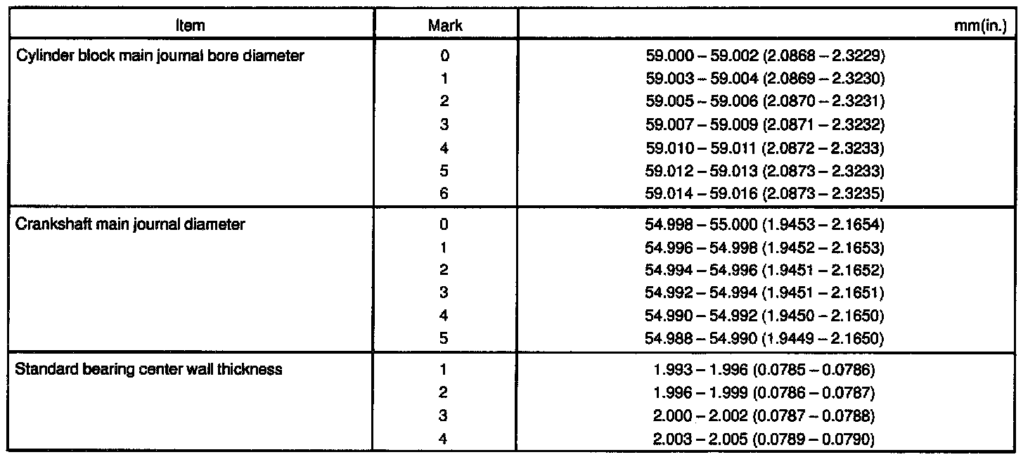
Reference
j Completely remove the Plastigage.
23. REMOVE CRANKSHAFT
a Lift out the crankshaft.
b Remove the 5 upper main bearings and 2 thrust washers from the cylinder block.
HINT: Arrange the main bearings and thrust washers in the correct order.
24. CHECK FIT BETWEEN PISTON AND PISTON PIN
Try to move the piston back and forth on the piston pin. If any movement is felt, replace the piston and pin as a set.
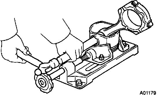
25. REMOVE PISTON RINGS
a Using a piston ring expander, remove the 2 compression rings.
b Remove the 2 side rails and oil ring by hand.
HINT: Arrange the piston rings in the correct order only.
26. DISCONNECT CONNECTING ROD FROM PISTON

a Using a small screwdriver, pry out the 2 snap rings.
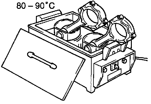
b Gradually heat the piston to 80 - 90°C (176 - 194°F).
c Using a plastic-faced hammer and a brass bar, lightly tap out the piston pin and remove the connecting rod.
HINT:
- The piston and pin are a matched set.
- Arrange the pistons, pins, rings, connecting rods and bearings in the correct order.