Disassembly and Reassembly
DISASSEMBLY1. REMOVE DUST PROTECTOR
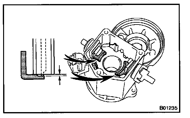
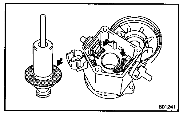
2. REMOVE FIELD FRAME AND ARMATURE
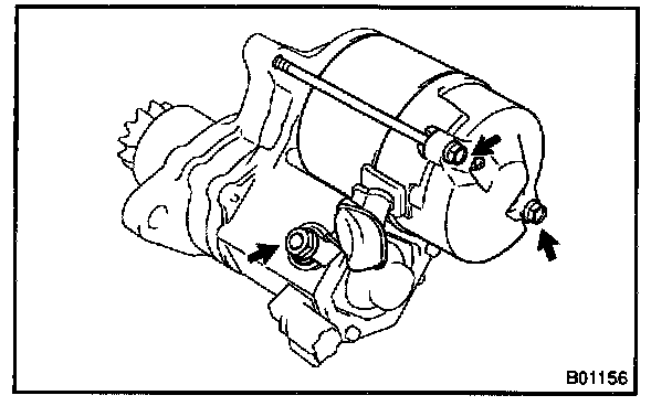
a. Remove the nut, and disconnect the lead wire from the magnetic switch terminal.
Torque: 5.9 N.m (60 kg.cm, 52 in.lb)
b. Remove the 2 through bolts.
Torque: 5.9 N.m (60 kg.cm, 52 in.lb)

c. Pull out the field frame together with the armature.
HINT: At the time of reassembly, align the protrusion of the field frame with the indentation of the magnetic switch.
d. Remove the O-ring from the field frame.
HINT: At the time of reassembly, use a new O-ring.
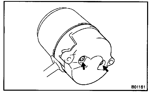
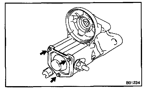
3. REMOVE STARTER HOUSING, CLUTCH ASSEMBLY AND GEAR
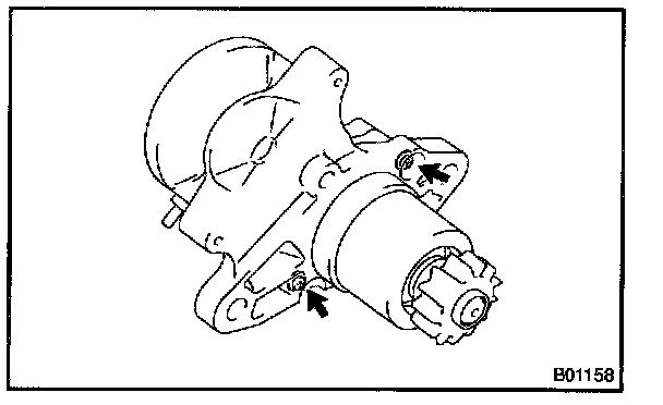
a. Remove the 2 screws.
Torque: 5.9 N.m (60 kg.cm, 52 in.lb)
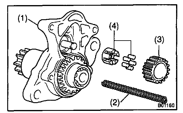
b. Remove the starter housing and clutch assembly (1), return spring (2), idler gear (3) and bearing from the magnetic switch.
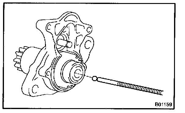
4. REMOVE STEEL BALL
Using a magnetic finger, remove the steel ball from the clutch shaft hole.
5. REMOVE BRUSH HOLDER
a. Remove the 2 screws and end cover from the field frame.
Torque: 1.5 N.m (15 kg.cm, 13 in.lb)
b. Remove the O-ring from the field frame.
c. Using a screwdriver, hold the spring back and disconnect the brush from the brush holder. Disconnect the 4 brushes, and remove the brush holder.
NOTE: At the time of reassembly, check that the positive (+) lead wires are not grounded.
6. REMOVE ARMATURE FROM FIELD FRAME
REASSEMBLY
REASSEMBLY is in the reverse order of disassembly.
HINT: Before reassembly, use high-temperature grease to lubricate the bearings, springs, steel ball and gears when assembling the starter.
REPLACEMENT
1. REPLACE CLUTCH ASSEMBLY
a. Disassemble the starter housing and the clutch assembly.
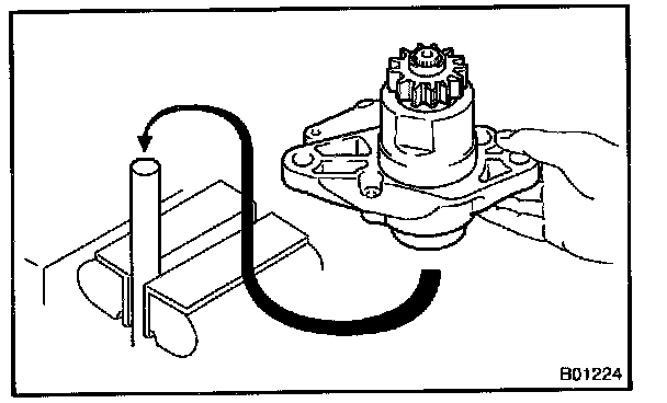
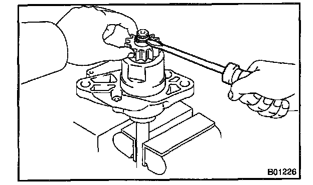
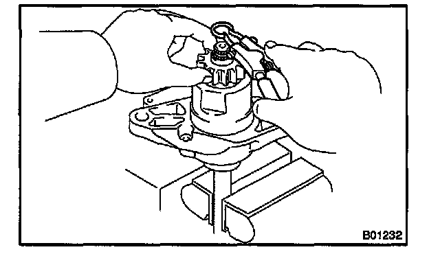
1. Mount a brass bar in a vise, and install the starter housing and clutch assembly to the brass bar.
2. Push down the pinion gear.
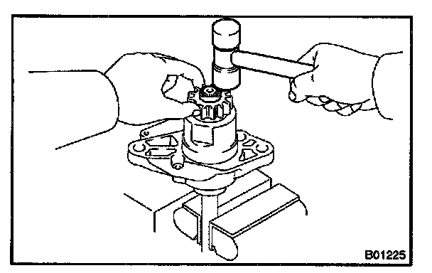
3. Using a plastic-faced hammer, tap down the stop collar.
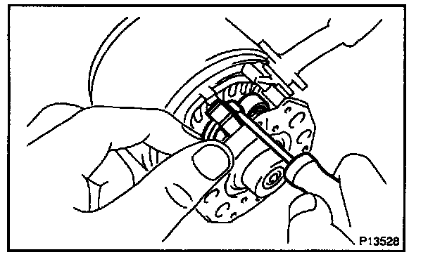
4. Using a screwdriver, pry out the snap ring.
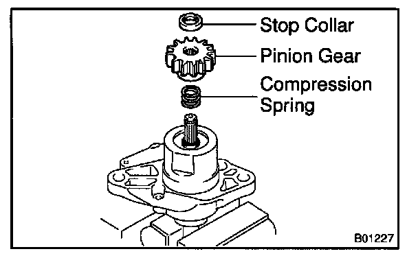
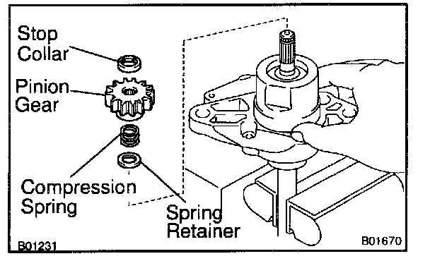
5. Remove the stop collar, pinion and compression spring.
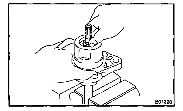
6. Push down the starter housing, and remove the spring retainer.
7. Remove the clutch shaft, compression spring and starter clutch from the starter housing.
b. Assemble the starter housing and the clutch assembly.
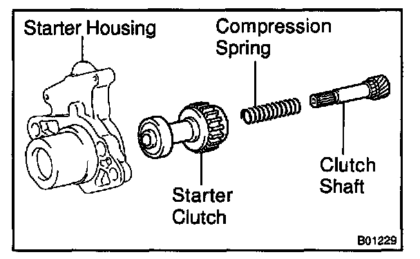
1. Install the starter clutch, compression spring, and clutch shaft to the starter housing.

2. Mount a brass bar in a vise, install the starter housing and clutch assembly to the brass bar.
3. Push down the starter housing,and Install the spring retainer, compression spring, pinion gear and stop collar.
4. Push down the pinion gear.
5. Using snap ring pliers, install a new snap ring.
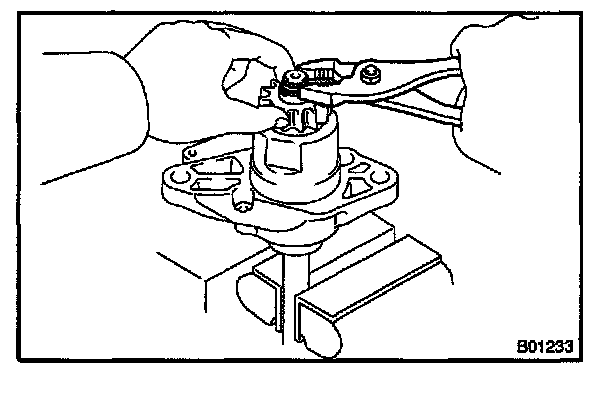
6. Using pliers, compress the snap ring.
7. Check that the snap ring fits correctly.
8. Remove the starter housing and clutch assembly from the brass bar.
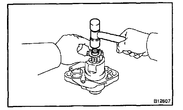
9. Using a plastic-faced hammer, tap the clutch shaft and install the stop collar onto the snap ring.
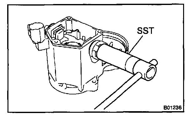
2. REPLACE FRONT BEARING
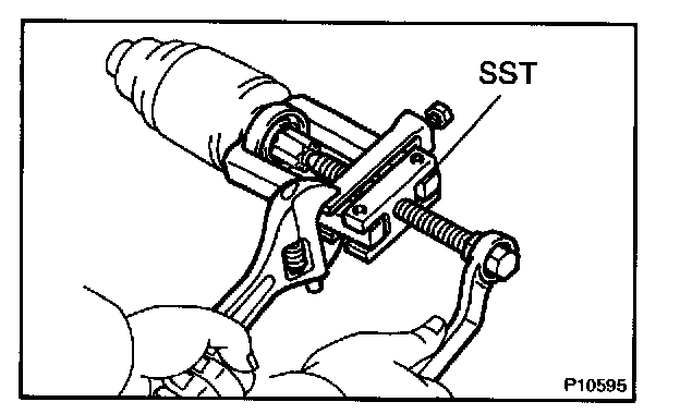
a. Using SST, remove the bearing.
SST 09286-46011
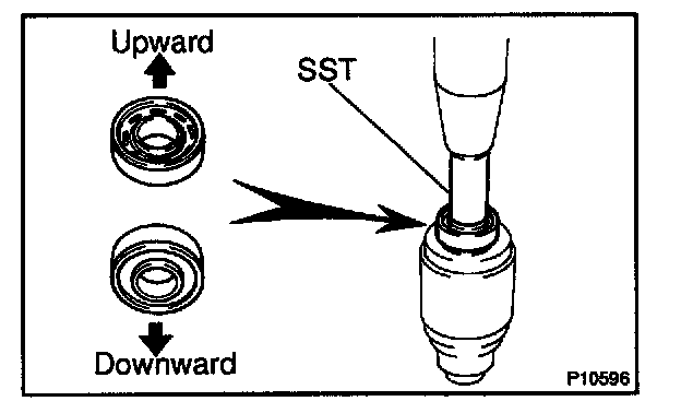
b. Using SST and a press, press in a new bearing.
NOTE: Be careful of the bearing installation direction.
SST 09820-00030
3. REPLACE REAR BEARING
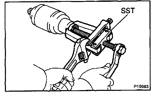
a. Using SST, remove the bearing.
SST 09286-46011
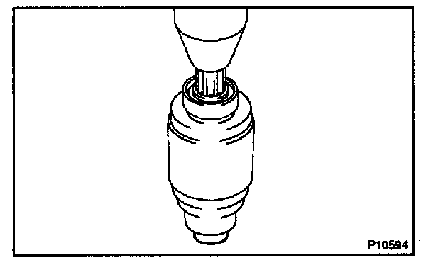
b. Using a press, press in a new bearing.
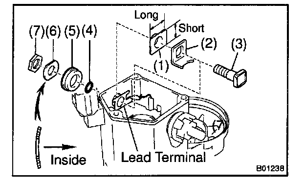
4. REPLACE MAGNETIC SWITCH TERMINAL KIT PARTS
a. Remove the 3 bolts, end cover, gasket and plunger.
b. Using vernier calipers, measure the contact plate for depth of wear.
Maximum wear: 0.9 mm (0.035 in.)
If the depth of wear is greater than the maximum, replace the contact plate.
c. Remove the terminal kit parts.
1. Using SST, loosen the terminal nuts.
SST 09810-38140
2. Terminal C:
Remove the terminal nut, wave washer, terminal insulator (outside), O-ring, terminal bolt, contact plate and terminal insulator (inside).
3. Terminal 30:
Remove the terminal nut, wave washer, terminal insulator (outside), packing, O-ring, terminal bolt, contact plate, and terminal insulator (inside).
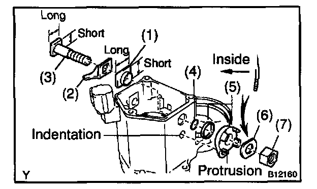
d. Temporarily install new terminal 30 kit parts:
1. Install a new terminal insulator (inside).
NOTE: Be careful to install the terminal insulator in the correct direction.
2. Install a new contact plate.
3. Install a new terminal bolt.
4. Install a new O-ring.
5. Install a new packing to anew terminal insulator, and install them.
HINT: Match the protrusion of the insulator with the indentation of the housing.
6. Install a new wave washer.
NOTE: Be careful to install the wave washers in the correct direction.
7. Install a new terminal nut.
Temporarily tighten the terminal nut.
e. Temporarily install new terminal C kit parts:
1. Install a new terminal insulator (inside).
NOTE: Be careful to install the terminal insulator in the correct direction.
2. Install a new contact plate.
3. Install a new terminal bolt.
4. Install a new O-ring.
5. Install a new terminal insulator (outside).
6. Install a new wave washer.
NOTE: Be careful to install the wave washer in the correct direction.
7. Install a new terminal nut.
Temporarily tighten the terminal nut.
f. Tighten terminal nuts.
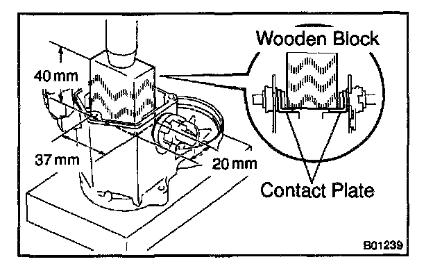
1. Put a wooden block on the contact plate and press it down with a hand press.
Dimensions of wooden block: 20 x 37 x 40 mm (0.79 x 1.46 x 1.57 in.)
Press force: 981 N (100 kg, 221 lb)
NOTE:
- Check the diameter of the hand press ram. Then calculate the gauge pressure of the press when 981 N (100 kg, 221 lb) of force is applied.
Gauge Pressure:
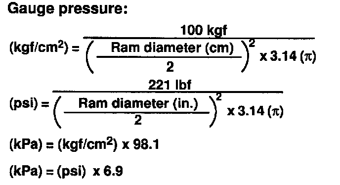
Gauge Pressure
- If the contact plate is not pressed down with the specified pressure, the contact plate may tilt due to coil deformation or the tightening of the nut.
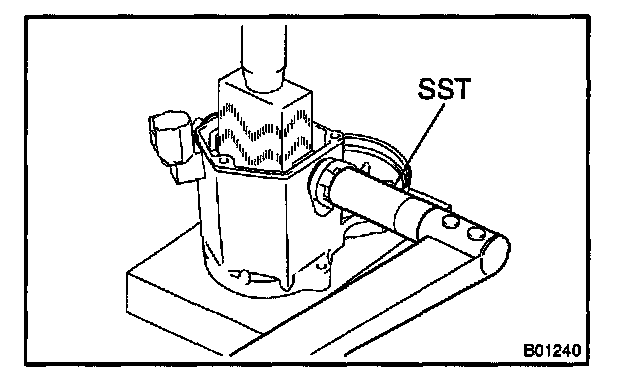
2. Using SST, tighten the nuts to the specified torque.
SST 09810-38140
Torque: 17 N.m (173 kg.cm, 13 ft.lb)
NOTE: If the nut is over tightened, it may cause cracks on the inside of the insulator.
g. Clean the contact surfaces of the remaining contact plate and plunger with a dry shop rag.
h. Reinstall the plunger, a new gasket and the end cover with the 3 bolts.
Torque: 2.5 N.m (26 kg.cm, 23 in.lb)