Automatic Transaxle Replacement
AUTOMATIC TRANSAXLE UNIT [U241E]:

AUTOMATIC TRANSAXLE UNIT [U241E]:

REMOVAL
1. REMOVE HOOD
Torque: 13 Nm (130 kgf-cm, 9 ft. lbs.)
2. REMOVE AIR CLEANER ASSEMBLY
3. REMOVE ENGINE COOLANT RESERVOIR
4. REMOVE ENGINE UNDER COVERS
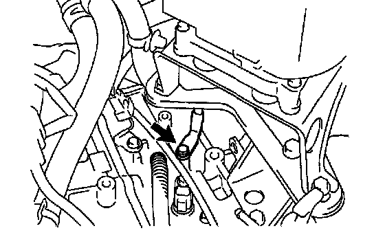
5. DISCONNECT SHIFT CONTROL CABLE
a. Remove the nut from the control shaft lever.
Torque: 15 Nm (150 kgf-cm, 11 ft. lbs.)
b. Remove the clip, and disconnect the control cable from the bracket.
c. Disconnect the control cable from the cable clamp on the transaxle.

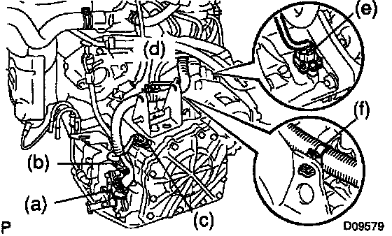
6. REMOVE STARTER
a. Disconnect the hose from the ATF level gauge guide.
b. Disconnect the starter connector.
c. Disconnect the wire clamp on starter wire from the bracket.
d. Remove the 2 bolts, and pull out the starter.
Torque: 37 Nm (380 kgf-cm, 27 ft. lbs.)
e. Remove the nut and disconnect the starter wire.
Torque: 13 Nm (130 kgf-cm, 10 ft. lbs.)
f. Remove the starter.
7. DISCONNECT GROUND CABLE
Remove the bolt, and disconnect the ground cable.
Torque: 19 Nm (195 kgf-cm, 14 ft. lbs.)
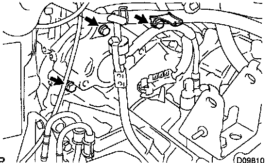
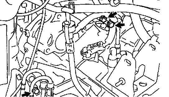
8. DISCONNECT CONNECTORS AND WIRE CLAMP
a. Disconnect the park/neutral position switch connector.
b. Disconnect the solenoid wire connector.
c. Disconnect the input turbine speed sensor connector.
d. Disconnect the counter gear speed sensor connector.
e. Disconnect the vehicle speed sensor connector.
f. Disconnect the wire harness clamp from the engine mounting bracket.
9. REMOVE 3 UPPER SIDE TRANSAXLE MOUNTING BOLTS AND WIRE CLAMP BRACKET
Torque: 64 Nm (653 kgf-cm, 47 ft. lbs.)
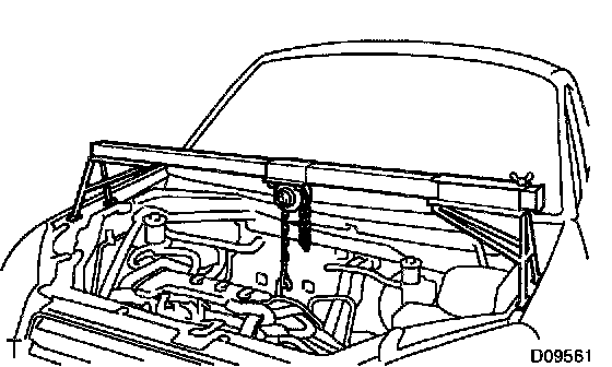
10. INSTALL ENGINE SUPPORT FIXTURE
11. REMOVE ENGINE LEFT MOUNTING BOLT AND NUT
Torque: 56 Nm (571 kgf-cm, 41 ft. lbs.)
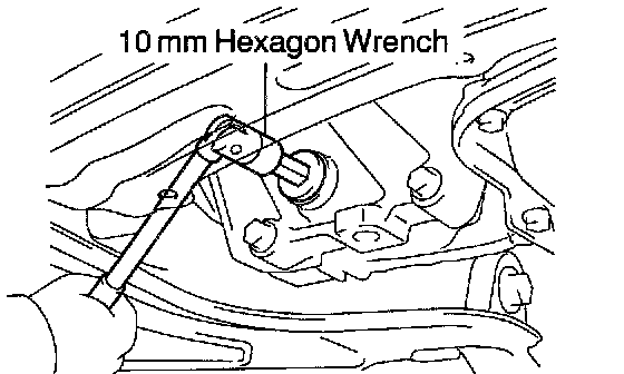
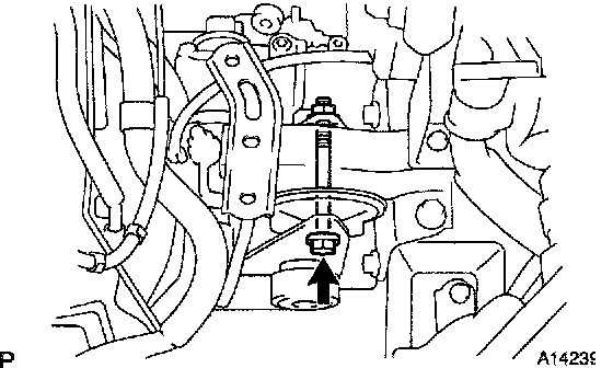
12. DRAIN ATF FROM DIFFERENTIAL CASE
Using a 10 mm hexagon wrench, remove the drain plug and gasket, and drain ATF.
HINT: At the time of installation, use a new gasket.
Torque: 54 Nm (550 kgf-cm, 40 ft. lbs.)
13. REMOVE LH AND RH DRIVE SHAFTS
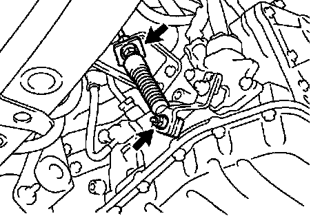
14. REMOVE FRONT EXHAUST PIPE
Remove the 4 bolts, 2 springs, front exhaust pipe and 2 gaskets.
HINT: At the time of installation, use 2 new gaskets.
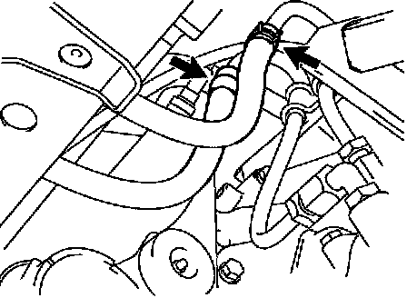
15. DISCONNECT 2 OIL COOLER HOSES FROM TRANSAXLE
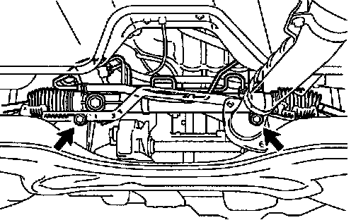
16. REMOVE POWER STEERING GEAR MOUNTING BOLTS
Torque: 137 Nm (1,400 kgf-cm, 101 ft. lbs.)
NOTICE: Support the power steering gear housing securely.
17. REMOVE FRONT SUSPENSION CROSSMEMBER ASSEMBLY WITH STABILIZER BAR
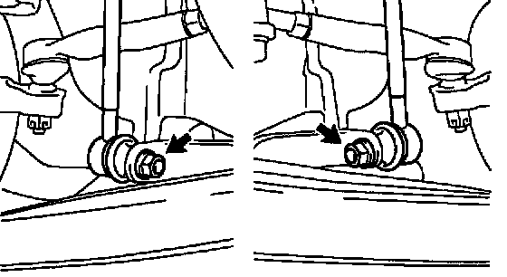
a. Remove the 2 nut, and disconnect the 2 stabilizer bar links from the stabilizer.
Torque: 44 Nm (450 kgf-cm, 32 ft. lbs.)
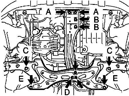
b. Remove the 3 bolts, 2 nuts and front suspension crossmember assembly with stabilizer bar.
Torque:
Bolt A: 39 Nm (400 kgf-cm, 28 ft. lbs.)
Bolt B: 80 Nm (820 kgf-cm, 59 ft. lbs.)
Bolt C: 113 Nm (1,150 kgf-cm, 80 ft. lbs.)
Bolt D: 115 Nm (1,170 kgf-cm, 85 ft. lbs.)
Bolt E: 157 Nm (1,600 kgf-cm, 115 ft. lbs.)
Nut: 115 Nm (1,170 kgf-cm, 85 ft. lbs.)

18. REMOVE TORQUE CONVERTER CLUTCH MOUNTING BOLT
a. Remove the hole plug.
b. Turn the crankshaft to gain access to each bolt, remove the holding the crankshaft pulley bolt with a wrench.
Torque: 41 Nm (420 kgf-cm, 32 ft. lbs.)
HINT: At the time of installation, first install the green colored bolt and then the 5 other bolts.

19. REMOVE 4 TRANSAXLE LOWER SIDE MOUNTING BOLTS
Torque: 44 Nm (449 kgf-cm, 32 ft. lbs.)
20. REMOVE TRANSAXLE
Remove the front side transaxle mounting bolt, 2 rear side transaxle mounting bolts and transaxle.
Torque: 46 Nm (469 kgf-cm, 34 ft. lbs.)
INSTALLATION
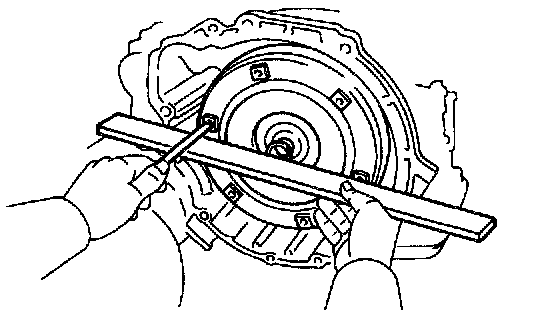
1. CHECK TORQUE CONVERTER CLUTCH INSTALLATION
Using calipers and a straight edge, measure the distance between the installed surface and the front surface of the transaxle housing.
Correct distance: More than 12.95 mm (0.510 inch)
2. TRANSAXLE INSTALLATION
Installation is in the reverse order of removal.
HINT:
^ After installation, adjust the shift control cable and park neutral position switch.
^ Fill ATF and check the fluid level.
^ Perform the test drive of the vehicle.
^ Adjust the hood.