Part 2
REPLACEMENT41. REMOVE IDLER PULLEY SUB-ASSY NO.2
a) Remove the 2 bolts and 2 idler pulleys.
42. REMOVE IDLER PULLEY SUB-ASSY NO.1
a) Remove the bolt and idler pulley.
43. REMOVE V-RIBBED BELT TENSIONER ASSY
44. REMOVE WATER INLET
45. REMOVE OIL FILTER BRACKET SUB-ASSY
a) Remove the 3 bolts, 2 nuts, oil filter bracket and gasket.
46. REMOVE INTAKE MANIFOLD
47.REMOVE CAMSHAFT TIMING OIL CONTROL VALVE ASSY
a)Remove the 2 bolts and 2 camshaft timing oil control valves
48. REMOVE WATER BY-PASS JOINT RR
49. REMOVE OIL FILLER CAP SUB-ASSY
50. REMOVE OIL FILLER CAP HOUSING.
a) Remove the 2 nuts, oil filler cap housing and gasket.
51. REMOVE IGNITION COIL ASSY
52. REMOVE SPARK PLUG
53. REMOVE OIL LEVEL GAUGE SUB-ASSY
54. REPLACE PARTIAL ENGINE ASSY
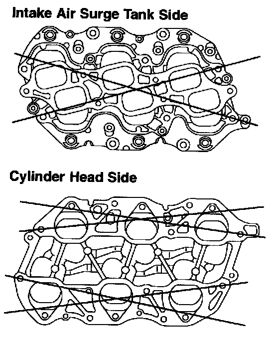
55. INSPECT INTAKE MANIFOLD FOR FLATNESS
a) Using a precision straight edge and feeler gauge, measure flatness for the surface contacted the cylinder head and intake air surge tank.
Maximum warpage:
Intake air surge tank side: 0.8 mm (0.031 inch)
Cylinder head side: 0.2 mm (0.008 inch)
If warpage is greater than maximum, replace the intake manifold.
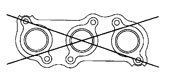
56. INSPECT EXHAUST MANIFOLD FOR FLATNESS
a) Using a precision straight edge and feeler gauge, measure flatness for the surface contacted the cylinder head.
Maximum warpage: 0.7 mm (0.028 inch)
If warpage is greater than maximum, replace the exhaust manifold.
HINT: Maximum warpage of each installation surface: 0.3 mm (0.012 inch)
57. INSTALL OIL LEVEL GAUGE SUB-ASSY
58. INSTALL SPARK PLUG
Torque: 20 Nm (204 kgf-cm, 15 ft. lbs.)
59. INSTALL IGNITION COIL ASSY
Torque: 9.0 Nm (92 kgf-cm, 80 inch lbs.)
60. INSTALL OIL FILLER CAP HOUSING
a) Install a new gasket and oil filler cap housing with the 2 nuts.
Torque: 9.0 Nm (92 kgf-cm, 80 inch lbs.)
61. INSTALL OIL FILLER CAP SUB-ASSY
62. INSTALL WATER BY-PASS JOINT RR
63. INSTALL CAMSHAFT TIMING OIL CONTROL VALVE ASSY
a) Insert the camshaft timing oil control valves to each cylinder head, and tighten the 2 bolts.
Torque: 9.0 Nm (92 kgf-cm, 80 inch lbs.)
64. INSTALL INTAKE MANIFOLD
65. INSTALL OIL FILTER BRACKET SUB-ASSY
a) Install a new gasket and oil filter bracket with the 3 bolts and 2 nuts.
Torque: 19 Nm (194 kgf-cm, 14 ft. lbs.)
66. INSTALL WATER INLET
67. INSTALL V-RIBBED BELT TENSIONER ASSY
68. INSTALL IDLER PULLEY SUB-ASSY NO.1
69. INSTALL IDLER PULLEY SUB-ASSY NO.2
70. INSTALL ENGINE MOUNTING BRACKET FRONT NO. 1 LH
a) install the engine mounting bracket w/engine mounting insulator with the 3 bolts.
Torque: 43 Nm (435 kgf-cm, 31 ft. lbs.)
71. INSTALL ENGINE MOUNTING BRACKET FRONT NO. 1 RH
a) Install the engine mounting bracket w/ engine mounting insulator with the 4 bolts.
Torque: 43 Nm (435 kgf-cm, 31 ft. lbs.)
72. INSTALL EXHAUST MANIFOLD SUB-ASSY LH
73. INSTALL EXHAUST MANIFOLD SUB-ASSY RH
74. INSTALL VENTILATION HOSE No. 2
75. INSTALL VENTILATION HOSE
76. INSTALL HEATER WATER OUTLET HOSE A (FROM HEATER UNIT)
77. INSTALL HEATER WATER INLET HOSE A
78. INSTALL RADIATOR OUTLET, NO.2 HOSE CLAMP OR CLIP
79. INSTALL RADIATOR HOSE NO.1
80. INSTALL ENGINE WIRE