Part 2
Part 1 Of 9:

Part 2 Of 9:

Part 3 Of 9:

Part 4 Of 9:

Part 5 Of 9:

Part 6 Of 9:

Part 7 Of 9:

Part 8 Of 9:

Part 9 Of 9:

PARTIAL ENGINE ASSY
REPLACEMENT
41. DISCONNECT STEERING INTERMEDIATE SHAFT SUB-ASSY
a. Loosen the sliding yoke bolt.
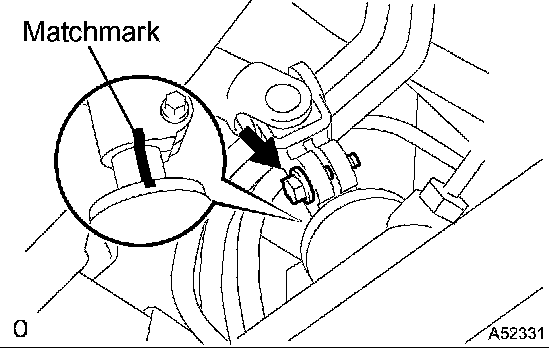
b. Place matchmarks on the intermediate shaft and control valve shaft.
c. Remove the bolt and the steering intermediate shaft.
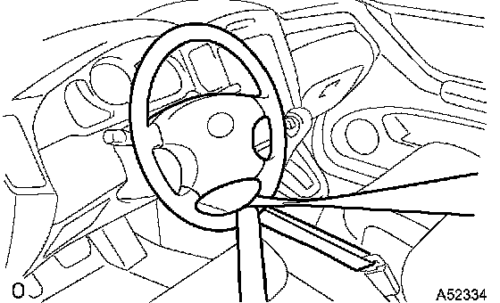
d. To prevent the steering wheel from rotating, fix the wheel with the seat belt.
NOTICE: If the steering wheel is not fixed, the spiral cable will be damaged.
42. DISCONNECT COMPRESSOR AND MAGNETIC CLUTCH
HINT: Hung up the hoses instead of detaching.
43. REMOVE ENGINE ASSEMBLY WITH TRANSAXLE
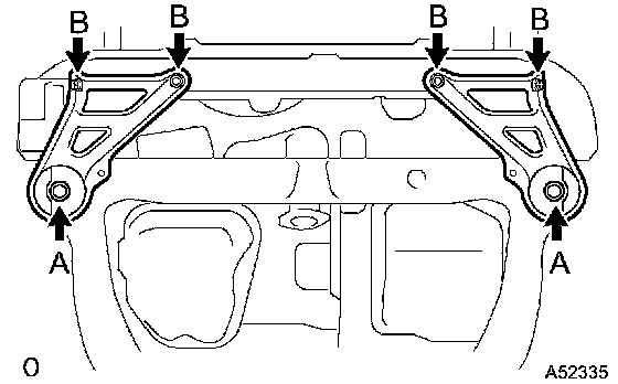
a. Set the engine lifter.
b. Remove the 6 bolts and frame side rail plate RH and LH.
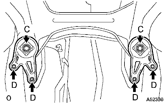
c. Remove the 6 bolts and front suspension member brace rear RH and LH.
d. Carefully remove the engine assembly from the vehicle.
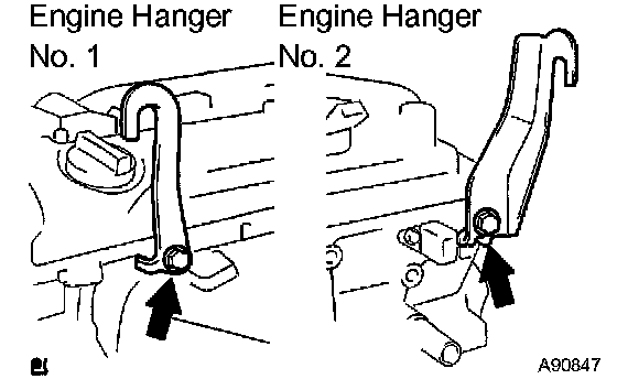
e. Install the 2 engine hangers as shown in the illustration.
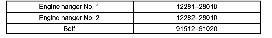
Parts No.
Torque: 38 Nm (387 kgf-cm, 28 ft. lbs.)
Using a chain block and an engine sling device, hang the engine assembly.
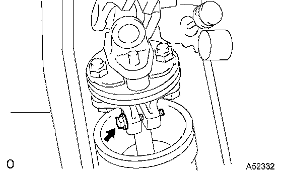
44. REMOVE VANE PUMP ASSY
a. Disconnect the PS oil pressure switch connector.
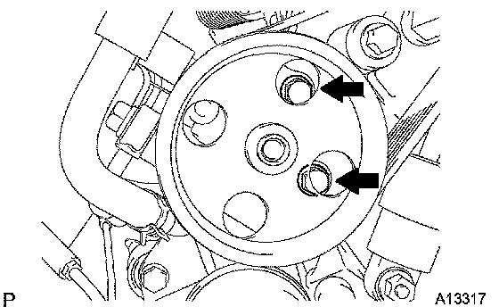
b. Remove the 2 bolts and vane pump from the engine.
45. REMOVE STABILIZER BAR FRONT (4WD TYPE)
46. REMOVE RACK & PINION POWER STEERING GEAR ASSY (4WD TYPE)
47. REMOVE FRONT FRAME ASSY
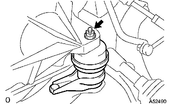
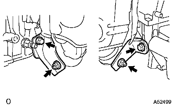
a. Remove the nut installing the engine mounting insulator LH.
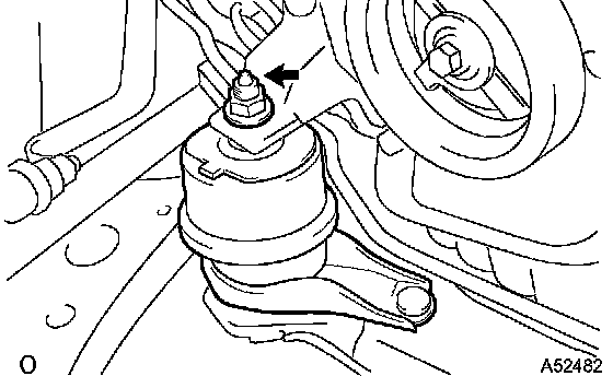
b. Remove the nut installing the engine mounting insulator RH.
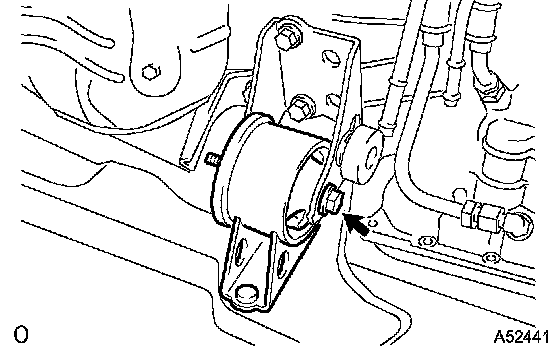
c. Remove the nut installing the engine mounting insulator FR.
48. REMOVE FRONT DRIVE SHAFT ASSY RH (4WD TYPE)
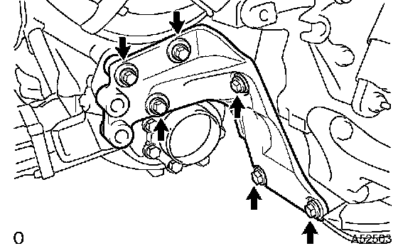
49. REMOVE ENGINE MOUNTING BRACKET RR (4WD TYPE)
a. Remove the 6 bolts and engine mounting bracket RR.
50. REMOVE TRANSFER ASSY (4WD TYPE)
51. REMOVE FRONT DRIVE SHAFT ASSY LH
52. REMOVE FRONT DRIVE SHAFT ASSY RH (2WD TYPE)
53. REMOVE STARTER ASSY
54. REMOVE AUTOMATIC TRANSAXLE ASSY
55. REMOVE DRIVE PLATE & RING GEAR SUB-ASSY
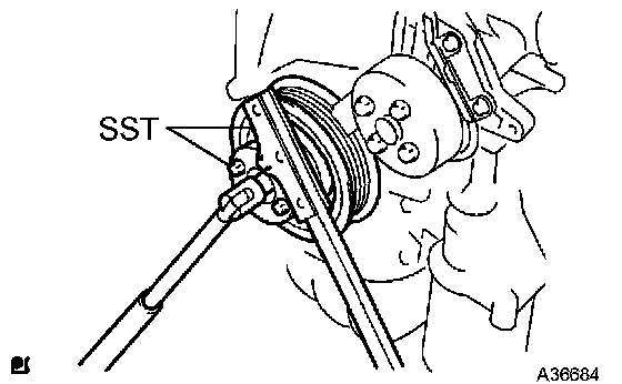
a. Using SST, fix the crankshaft.
SST 09213-54015 (91651-60855), 09330-00021
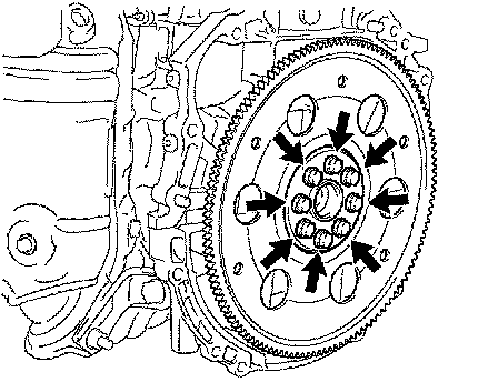
b. Remove the 8 bolts, rear spacer, drive plate and front spacer.
56. INSTALL ENGINE STAND
57. REMOVE ENGINE COVER SUB-ASSY NO.1
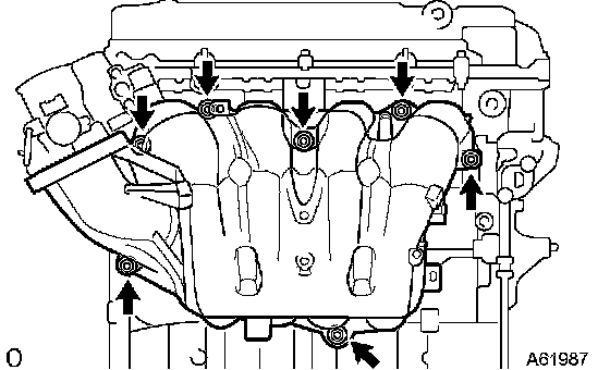
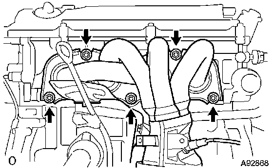
58. REMOVE INTAKE MANIFOLD
a. Remove the 5 bolts, 2 nuts, intake manifold and gasket.
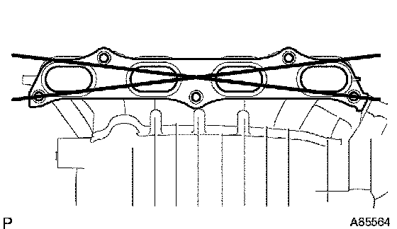
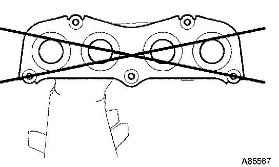
59. INSPECT INTAKE MANIFOLD
a. Using a precision straight edge and feeler gauge, measure the surface contacting the cylinder head for warpage.
Maximum warpage: 2.0 mm (0.079 inch)
If the warpage is greater than the maximum, replace the manifold.
60. REMOVE VENTILATION HOSE No.1
61. REMOVE VENTILATION HOSE NO.2
62. REMOVE ENGINE WIRE
63. REMOVE INTAKE MANIFOLD INSULATOR NO.1
64. REMOVE GENERATOR ASSY
65. REMOVE OIL LEVEL GAGE SUB-ASSY
66. REMOVE OIL LEVEL GAGE GUIDE
67. REMOVE MANIFOLD CONVERTER INSULATOR NO.1
68. REMOVE EXHAUST MANIFOLD CONVERTER SUB-ASSY
a. Remove the 3 bolts, 2 nuts, and the No. 1 and No. 2 exhaust manifold stays.
b. Remove the 5 nuts, exhaust manifold converter and gasket.
69. INSPECT EXHAUST MANIFOLD CONVERTER SUB-ASSY
a. Using a precision straight edge and feeler gauge, measure the surface contacting the cylinder head for warpage.
Maximum warpage: 0.70 mm (0.0276 inch)
If the warpage is greater than the maximum, replace the manifold.
70. REMOVE WATER INLET
71. REMOVE THERMOSTAT
72. REMOVE IGNITION COIL ASSY
73. REMOVE CAMSHAFT TIMING OIL CONTROL VALVE ASSY
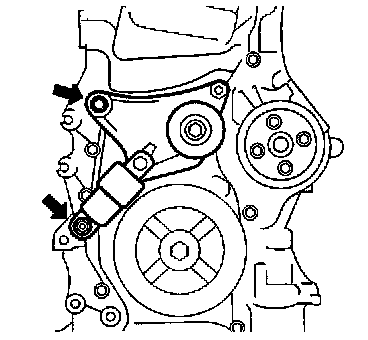
74. REMOVE V-RIBBED BELT TENSIONER ASSY
a. Remove the bolt, nut and belt tensioner.
75. REMOVE DRIVE SHAFT BEARING BRACKET (2WD TYPE)
76. REMOVE ENGINE MOUNTING BRACKET RH
77. REMOVE FUEL DELIVERY PIPE W/INJECTOR
78. REMOVE WATER BY-PASS PIPE NO.1
79. REMOVE OIL COOLER PIPE (W/ OIL COOLER)
80. REMOVE OIL COOLER HOSE (W/ OIL COOLER)