ABS/TCS - VSC Lamp ON/DTC C1234 Set
BRAKESBR004-03
Title:
DTC C1234. YAW RATE SENSOR
Models:
'04 Sienna
November 24, 2003
TSB REVISION NOTICE:
November 17, 2004: Production Change Information was updated with new VINs and drivetrain options.
Previous versions of this TSB should be discarded.
Introduction
In cases where the VSC indicator is illuminated and setting fault code DTC C1234, the yaw rate sensor may be setting an improper diagnostic code. Replace the yaw rate sensor with a new service part.
Applicable Vehicles
^ 2004 model year Sienna vehicles produced BEFORE the Production Change Effective VINs shown.

Production Change Information

Warranty Information
Applicable Warranty*:
This repair is covered under the Toyota Comprehensive Warranty. This warranty is in effect for 36 months or 36,000 miles, whichever occurs first, from the vehicle's in-service date.
* Warranty application is limited to correction of a problem based upon a customer's specific complaint.
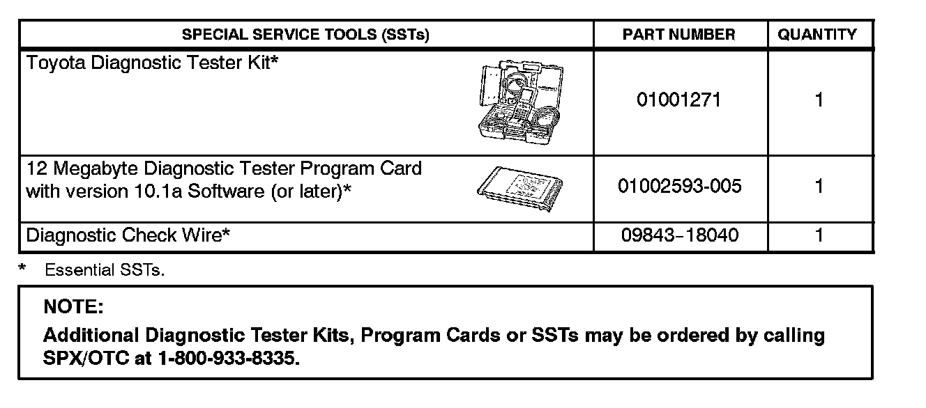
Required SSTs

Parts Information
Service Part Identification
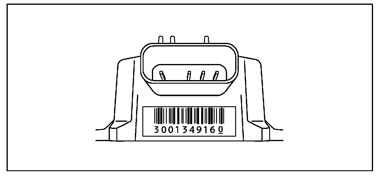
Countermeasure service parts are identified by the serial number (see bar code label) on the connector side of the sensor. There are 10 digits on the barcode label. The first 9 digits are the serial number. The Serial Number 300134916 and greater are the countermeasure parts.
Repair Procedure
The yaw rate sensor is located under the right front passenger seat. After replacing the yaw rate sensor, perform zero point calibration of the yaw rate sensor.
Zero Point Calibration Procedure With Diagnostic Tester
NOTE:
While obtaining the zero point, do not cause any vibration to the vehicle by tilting, moving, shaking, or starting the engine. Keep it in a stationary position. Be sure to perform this procedure on a level surface (within an inclination of 1%).
1. Move the gear selector to the "P" position.
2. Hook up the Diagnostic Tester to the DLC3.
3. Operate the Diagnostic Tester to clear zero point calibration.
4. Operate the Diagnostic Tester to Signal Check mode.
5. Turn the ignition switch "ON."
6. Keep the vehicle in the stationary condition on the level surface for 2 seconds or more.
7. Check that the VSC warning light blinks.
NOTE:
If the VSC warning light does not blink, perform the zero point calibration again.
8. Turn the ignition switch "OFF."
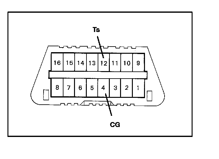
Zero Point Calibration Procedure Without Diagnostic Tester
NOTE:
While obtaining the zero point, do not cause any vibration to the vehicle by tilting, moving, shaking, or starting the engine. Keep it in a stationary position. Be sure to perform this procedure on a level surface (within an inclination of 1%).
1. Move the gear selector to the "P" position.
2. Clear the zero point calibration using the SST check wire.
^ SST P/N 09843-18040.
A. Turn the ignition switch "ON."
B. Using the SST at DLC3, connect and disconnect terminals Ts and CG four (4) times or more within 8 seconds.
C. Check that the VSC warning light is lit, indicating the recorded zero is erased.
D. Turn the ignition switch to "OFF" within 15 seconds. Disconnect the terminals of the DLC3.
E. Turn the ignition switch "ON."
F. Verify that the VSC light turns off in 15 seconds.
G. Turn the ignition switch "OFF."
3. Procedures for test modes:
A. Using the SST at DLC3, connect terminal Ts and CG.
B. Check that the steering wheel is in the straight-ahead position and move the gear selector to the "P" position.
C. Turn the ignition switch to "ON."
4. Keep the vehicle in a stationary position for two (2) seconds or more, on a level floor.
5. Check that the VSC warning light blinks.
6. If the VSC warning light does not blink, pe~orm the zero point calibration again.