Valve Body Assembly
ON-VEHICLE REPAIRCAUTION:
^ When working with FIPG material, you must observe the followings.
^ Using a razor blade and a gasket scraper, remove all old FIPG material from the gasket surfaces.
^ Thoroughly clean all components to remove all loose material.
^ Clean both sealing surfaces with a non-residue solvent.
^ Apply FIPG in an approx. 1 mm (0.04 inch) wide bead along the sealing surface.
^ Parts must be assembled within 10 minutes of application. Otherwise, the FIPG material must be removed and reapplied.
1. REMOVE DRAIN PLUG AND DRAIN ATF
2. REMOVE OIL PAN
NOTICE: Some fluid will remain in the oil pan.
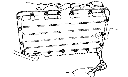
a. Remove the 19 bolts
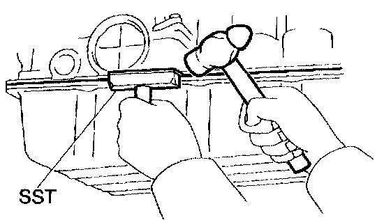
b. Install the blade of SST between the transmission case and oil pan, cut off applied sealer, and remove the oil pan
SST 09032-00100
NOTICE: When removing the oil pan, be careful not to damage the oil pan flange.
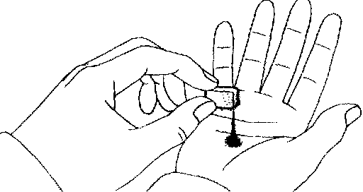
3. EXAMINE PARTICLES IN PAN
Remove the magnets and use them to collect steel particles
Carefully look at the foreign matter and particles in the pan and on the magnets to anticipate the type of wear you will find in the transmission
Steel (magnetic) bearing, gear and clutch plate wear
Brass (non-magnetic) bushing wear
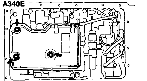
4. A340E: REMOVE OIL STRAINER
NOTICE: Be careful as some fluid will come out of the oil strainer.
a. Separate the solenoid wire.
b. Remove the 3 bolts, oil strainer and 2 gaskets.
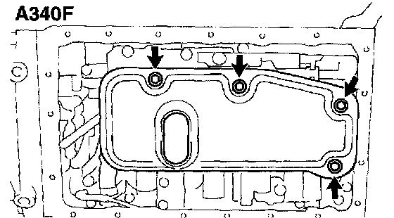
5. A340F: REMOVE OIL STRAINER
Remove the 4 bolts, oil strainer and 3 gaskets.
NOTICE: Be careful as some fluid will come out of the oil strainer.
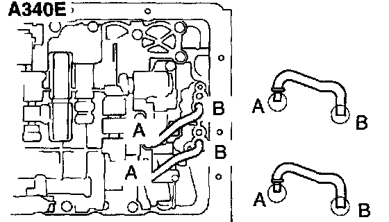
6. A340E: REMOVE OIL PIPE
Pry up both pipe ends with a large screwdriver and remove the 2 pipes.
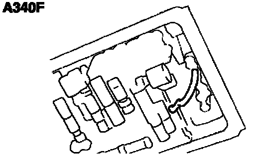
7. A340F: REMOVE OIL PIPE
Pry up both pipe ends with a large screwdriver and remove the pipe.
8. 3RZ-FE: REMOVE VALVE BODY
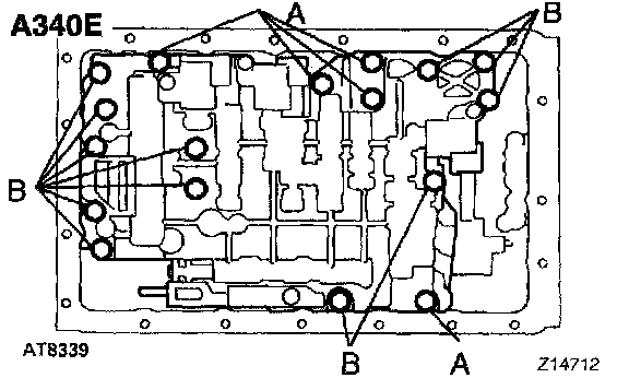
a. Disconnect the 3 connectors from each shift solenoid valves.
b. A340E: Remove the 17 bolts.
Bolt length:
Bolt A: 23 mm (0.91 inch)
Bolt B: 32 mm (1.26 inch)
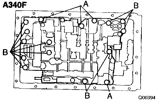
c. A340F: Remove the 16 bolts.
Bolt length:
Bolt A: 23 mm (0.91 inch)
Bolt B: 32 mm (1.26 inch)
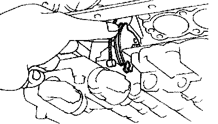
d. Disconnect the throttle cable from the cam.
e. Remove the valve body.
NOTICE: Be careful not to drop the check ball body and spring.
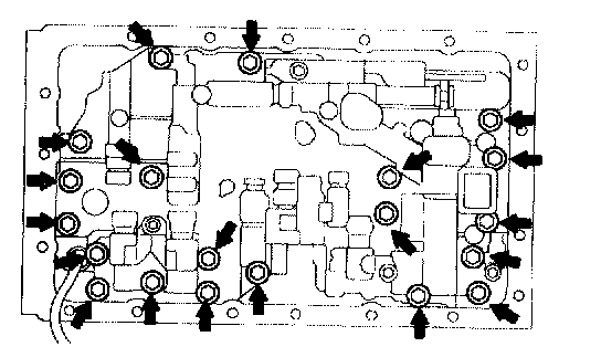
9. 5VZ-FE: REMOVE VALVE BODY
a. Disconnect the 4 connectors from each shift solenoid valves.
b. Remove the 20 bolts and valve body.
10. 3RZ-FE: REMOVE SHIFT SOLENOID VALVE
a. Remove the solenoid valve mounting bolts.
b. Remove the 3 solenoid valves.
c. Remove the 3 O-rings from the solenoid valves.
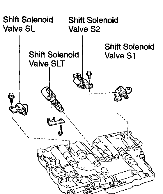
11. 5VZ-FE: REMOVE SHIFT SOLENOID VALVE
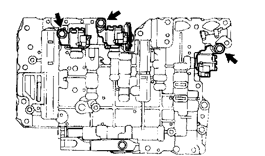
a. Remove the 2 bolts and 3 shift solenoid valves.
b. Turn the valve body, remove the bolt, lock plate and shift solenoid valve.
c. Remove the 3 O-rings from the 3 solenoid valves.
12. 5VZ-FE: REMOVE DETENT SPRING
13. 5VZ-FE: REMOVE MANUAL VALVE
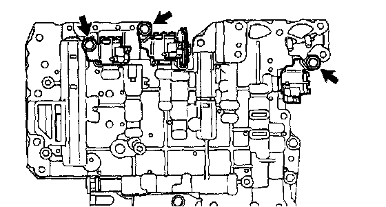
14. 3RZ-FE: INSTALL SHIFT SOLENOID VALVE
a. Coat the 3 new O-rings with ATF.
b. Install the 3 O-rings to the shift solenoid valves.
c. Install the 3 shift solenoid valves with the 3 bolts.
Torque: 10 Nm (100 kgf-cm, 7 ft. lbs.)
15. 5VZ-FE: INSTALL MANUAL VALVE
16. 5VZ-FE: INSTALL DETENT SPRING
Torque: 10 Nm (100 kgf-cm, 7 ft. lbs.)
17. 5VZ-FE: INSTALL SHIFT SOLENOID VALVE
a. Install 3 new O-rings to 3 shift solenoid valves.
b. Install the shift solenoid valve and lock plate with the bolt.
Torque: 10 Nm (100 kgf-cm, 7 ft. lbs.)
c. Install the 3 shift solenoid valves with the 2 bolts.
Torque: 10 Nm (100 kgf-cm, 7 ft. lbs.)
18. 3RZ-FE: INSTALL VALVE BODY
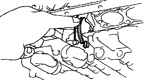
a. Align the groove of the manual valve to the pin of the lever.
b. Connect the throttle cable to the cam.
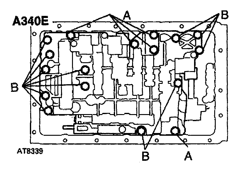
c. A340E: Install the 17 bolts.
Torque: 10 Nm (100 kgf-cm, 7 ft. lbs.)
Bolt length:
Bolt A: 23 mm (0.91 inch)
Bolt B: 32 mm (1.26 inch)
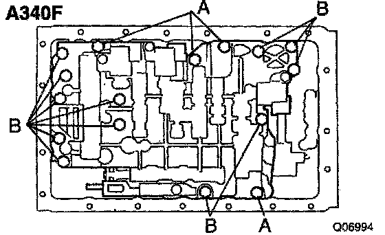
d. A340F: Install the 16 bolts
Torque: 10 Nm (100 kgf-cm, 7 ft. lbs.)
Bolt length:
Bolt A: 23 mm (0.91 inch)
Bolt B: 32 mm (1.26 inch)
e. Connect the 3 connectors to each shift solenoid valves.
19. 5VZ-FE: INSTALL VALVE BODY
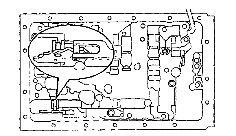
a. Align the groove of the manual valve with the pin of the lever
Install the valve body with the 20 bolts.
Torque: 11 Nm (110 kgf-cm, 8 ft. lbs.)
Bolt length:
Bolt A: 23 mm (0.91 inch)
Bolt B: 28 mm (1.10 inch)
Bolt C: 36 mm (1.42 inch)
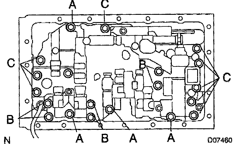
b. Connect the 4 connectors to each shift solenoid valves.
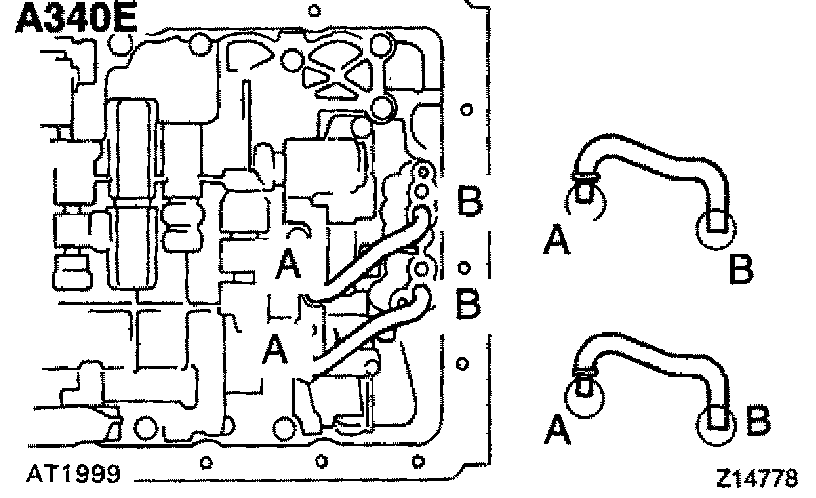
20. A340E: INSTALL OIL PIPE
Using a plastic hammer, install the 2 pipes into position.
NOTICE: Be careful not to bend or damage the pipes. Make sure that the oil pipes or magnet do not interfere with the oil pan.
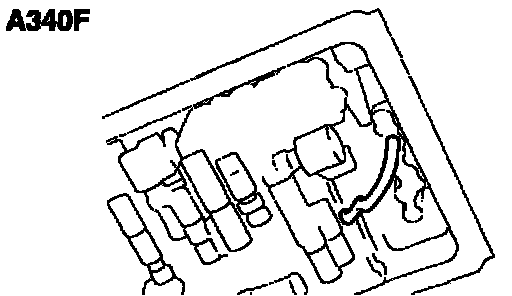
21. A340F: INSTALL OIL PIPE
Using a plastic hammer, install the pipe into position.
NOTICE: Be careful not to bend or damage the pipe. Make sure that the oil pipe or magnet do not interfere with the oil pan.
22. A340E: INSTALL OIL STRAINER
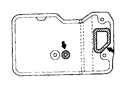
a. Install 2 new gaskets.
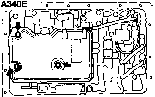
b. Install the oil strainer with the 3 bolts.
Torque: 10 Nm (100 kgf-cm, 7 ft. lbs.)
c. Clamp solenoid wire.
23. A340F: INSTALL OIL STRAINER
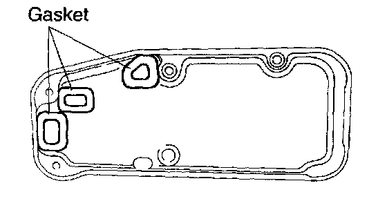
a. Install 3 new gaskets.
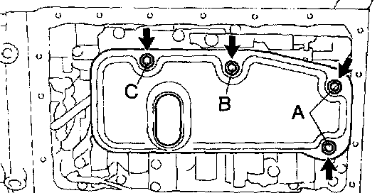
b. Install the oil strainer with the 4 bolts.
Torque: 10 Nm (100 kgf-cm, 7 ft. lbs.)
Bolt length:
Bolt A: 14 mm (0.55 inch)
Bolt B: 20 mm (0.79 inch)
Bolt C: 23 mm (0.91 inch)
24. INSTALL OIL PAN
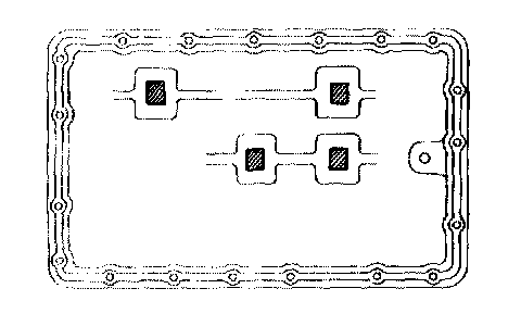
a. A340E: Install the 4 magnets in the indications of the oil pan.
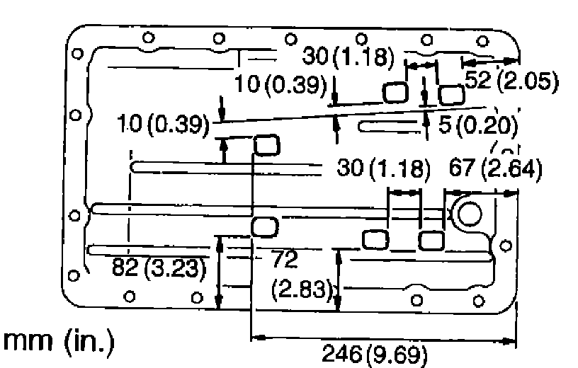
b. A340F: Install the 6 magnets in the indications of the oil pan.
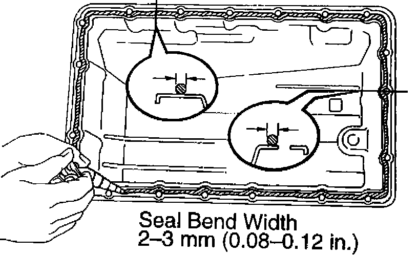
c. Remove any packing material and be careful not to drop oil on the contacting surfaces of the transmission case and oil pan.
d. Apply FIPG to the oil pan. FIPG: Part No. 08826-00090, THREE BOND 1281 or equivalent
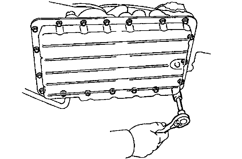
e. Install the oil pan with the 19 bolts.
Torque: 7.4 Nm (75 kgf-cm, 65 inch lbs.)
25. INSTALL DRAIN PLUG
Torque: 20 Nm (205 kgf-cm, 15 ft. lbs.)
26. FILL AND CHECK ATF