Except Double Cab
INSPECTION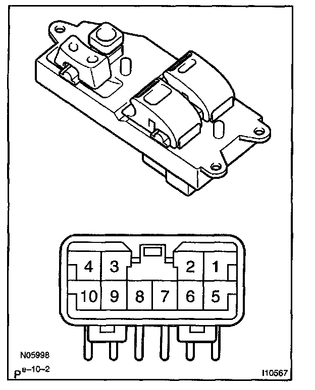
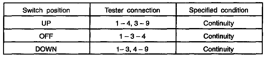
Driver's Switch:
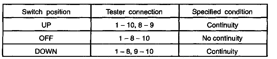
Passenger's Switch : Window Unlock:
Passenger's Switch : Window Lock:
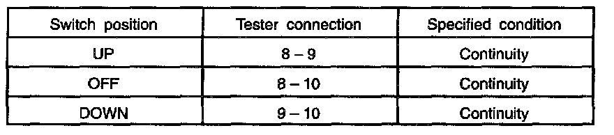
1. INSPECT POWER WINDOW MASTER SWITCH CONTINUITY
If continuity is not as specified, replace the switch.
2. INSPECT ONE-TOUCH POWER WINDOW SYSTEM CURRENT OF CIRCUIT (Using an ammeter)
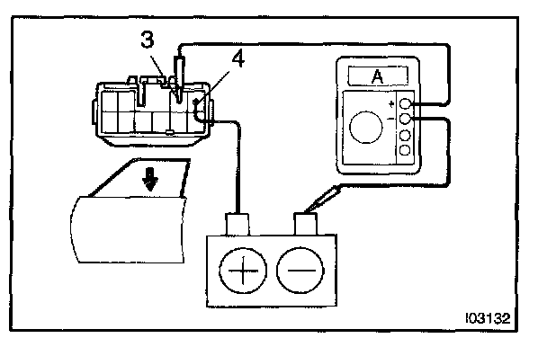
a. Disconnect the connector from the master switch.
b. Connect the positive (+) lead from the ammeter to terminal 3 on the wire harness side connector and the negative (-) lead to negative (-) terminal of the battery.
c. Connect the positive (+) lead from the battery to terminal 4 on the wire harness side connector.
d. As the window goes down, check that the current flow is approximately 7 A.
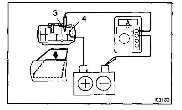
e. Check that the current increases up to approximately 14.5 A or more when the window stops going down.
HINT: The circuit breaker opens some 4 - 90 seconds after the window stops going down, so that check must be done before the circuit brake operates.
If the operation is not as specified, replace the switch.
3. INSPECT ONE-TOUCH POWER WINDOW SYSTEM/CURRENT OF CIRCUIT (Using an ammeter with a current-measuring probe)
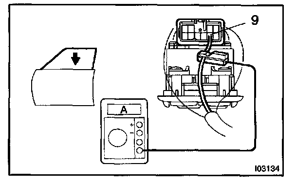
a. Remove the master switch with connector connected.
b. Attach a current-measuring probe to terminal 9 of the wire harness.
c. Turn the ignition switch ON and set power window switch in the down position.
d. As the window goes down, check that the current flow is approximately 7 A.
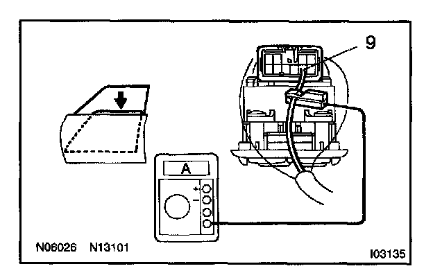
e. Check that the current increases up to approximately 14.5 A or more when the window stops going down.
HINT: The circuit breaker opens some 4 - 40 seconds after the window stops going down, so that check must be done before the circuit breaker operates.
If operation is not as specified, replace the master switch.
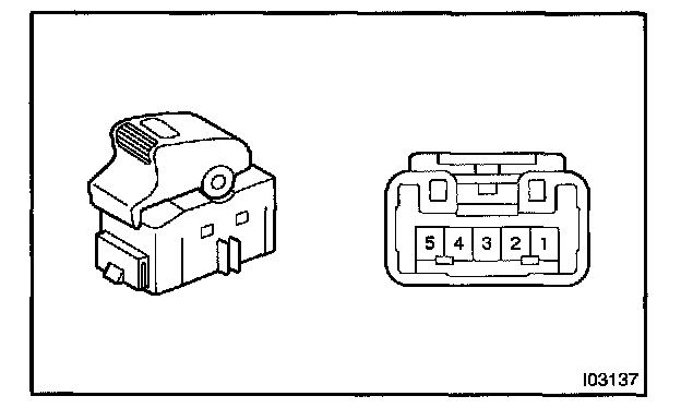
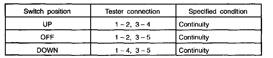
4. INSPECT POWER WINDOW SWITCH CONTINUITY
If continuity is not as specified, replace the switch.
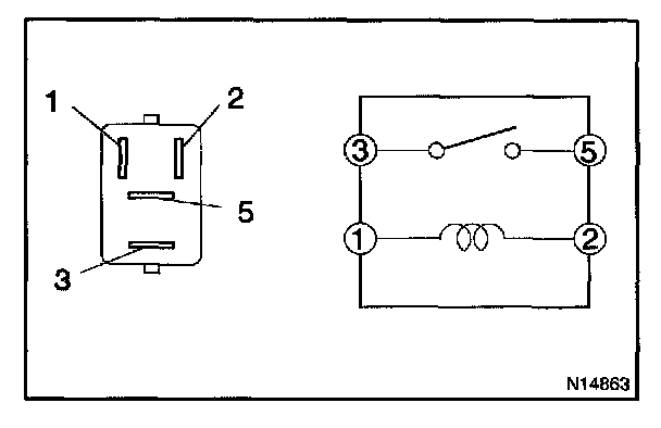
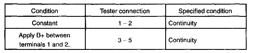
5. INSPECT POWER MAIN RELAY CONTINUITY
If continuity is not as specified, replace the switch.
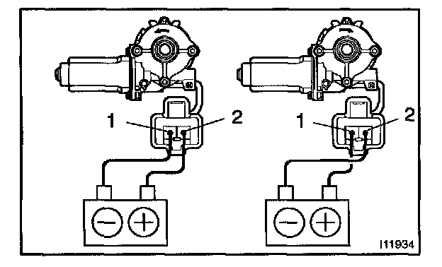
6. Driver's door
INSPECT POWER WINDOW MOTOR OPERATION
a. Connect the positive (+) lead from the battery terminal 2 and the negative (-) lead to terminal 1, and check that the motor turns counter clockwise.
b. Reverse the polarity, check that the motor turns counter clockwise
If operation is not as specified, replace the motor.
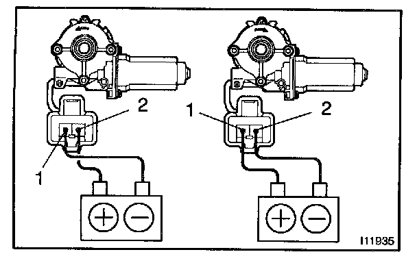
7. Passenger's door
INSPECT POWER WINDOW MOTOR OPERATION
a. Connect the positive (+) lead from the battery to terminal 2 and the negative (-) lead to terminal 1, and check that the motor turns counter clockwise.
b. Reverse the polarity, check that the motor turns clockwise.
If operation is not as specified, replace the motor.
8. Driver side door:
INSPECT POWER WINDOW MOTOR PTC THERMISTOR OPERATION
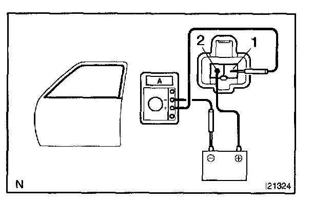
a. Disconnect the connector from the power window motor.
b. Connect the positive (+) lead from the ammeter to terminal 1 on the wire harness side connector and the negative (-) lead to the negative terminal of the battery.
c. Connect the positive (+) lead from the battery to terminal 2 on the wire harness side connector, and raise the window to the fully closed position.
d. Continue to apply voltage, and check that the current changes to less than 1 A in 4 to 90 seconds.
e. Disconnect the leads from the terminals.
f. Approximately 60 seconds later, connect the positive (+) lead from the battery to terminal 1 and the negative (-) lead to terminal 2, and check that the window begins to descend.
If the operation is not as specified, replace the motor.
9. Passenger side door:
INSPECT POWER WINDOW MOTOR PTC THERMISTOR OPERATION
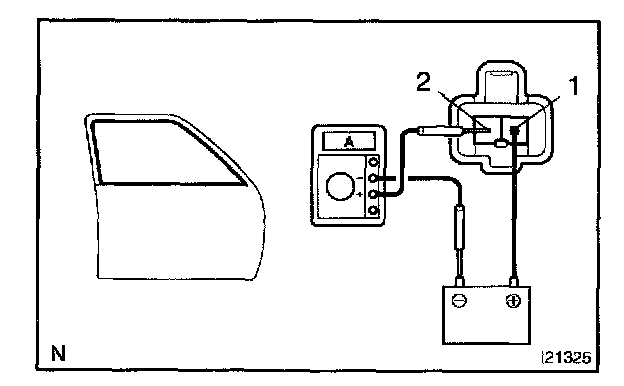
a. Disconnect the connector from the power window motor.
b. Connect the positive (+) lead from the ammeter to terminal 2 on the wire harness side connector and the negative (-) lead to the negative terminal of the battery.
c. Connect the positive (+) lead from the battery to terminal 1 on the wire harness side connector, and raise the window to the fully close position.
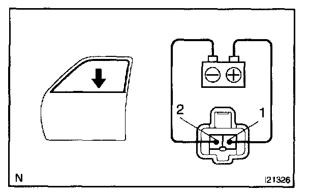
d. Continue to apply voltage and check that the current changes to less than 1 A in 4 to 90 seconds.
e. Disconnect the leads from the terminals.
f. Approximately 60 seconds later, connect the positive (+) lead from the battery to terminal 2 and the negative (-) lead to terminal 1, and check that the window begins to descend.
If the operation is not as specified, replace the motor.
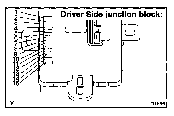
10. CHECK INTEGRATION RELAY
Remove the integration relay from the driver side junction block, and check the voltage or continuity of each terminal on the junction block side.