Pinout Values and Diagnostic Parameters
TERMINALS OF ECU
1. INSPECT INTEGRATION RELAY
a. Disconnect the I12 relay connector.
b. Measure the resistance between each terminal and the body ground.
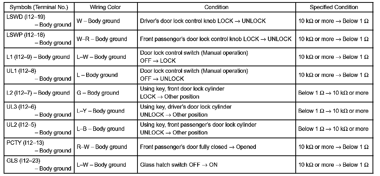
Standard:
If the result is not as specified, there may be a malfunction on the wire harness side.
c. Reconnect the connector.
d. Measure the resistance between each terminal and the body ground.
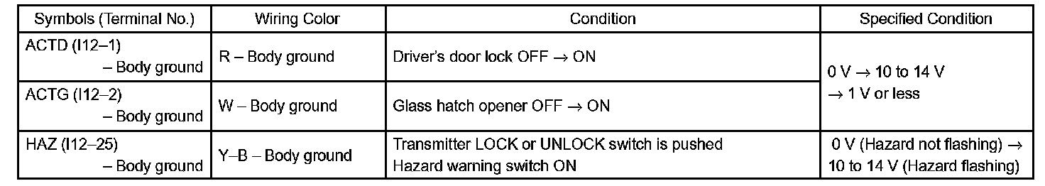
Standard:
If the result is not as specified, the integration relay may have a malfunction.
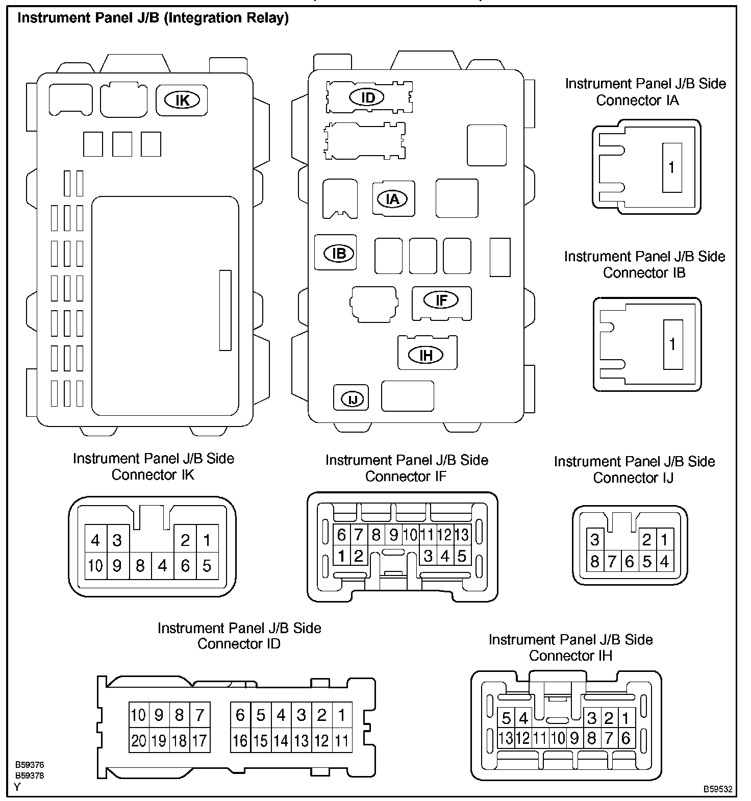
2. INSPECT INSTRUMENT PANEL J/B (INTEGRATION RELAY)
a. Disconnect the connectors IA, IB, ID, IF, IH and IJ the instrument panel J/B.
b. Measure the resistance and voltage between each terminal and the body ground.
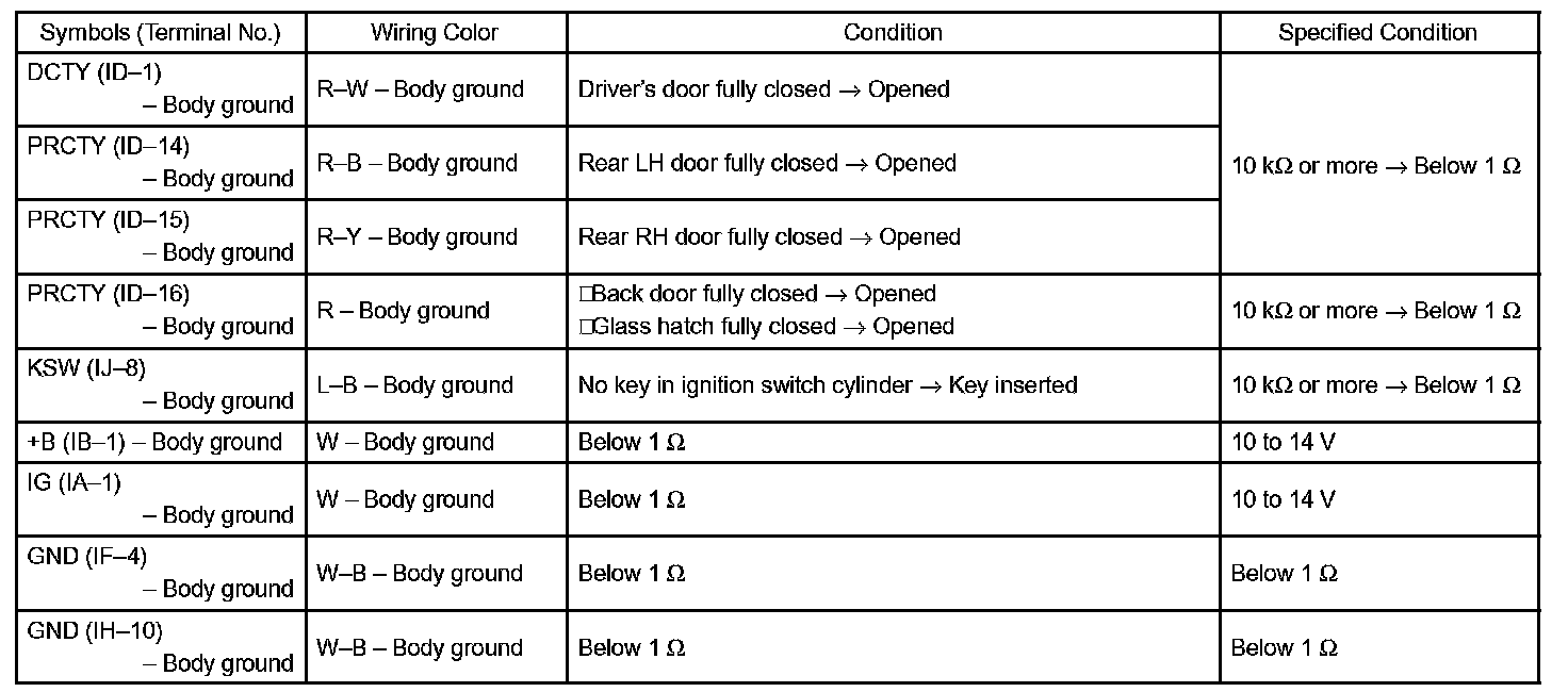
Standard:
If the result is not as specified, there my be a malfunction on the wire harness side.
c. Reconnect the connectors.
d. Measure the voltage between each terminal and body ground.
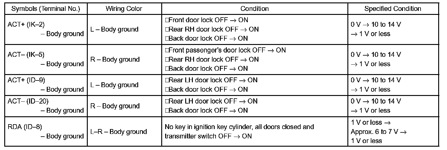
Standard:
If the result is not as specified, the integration relay or instrument panel J/B assembly may have a malfunction.