Engine Immobilizer System (W/ Smart Entry System)
TERMINALS OF ECUTerminals Of Control Module/Pinouts - Check Key Slot:
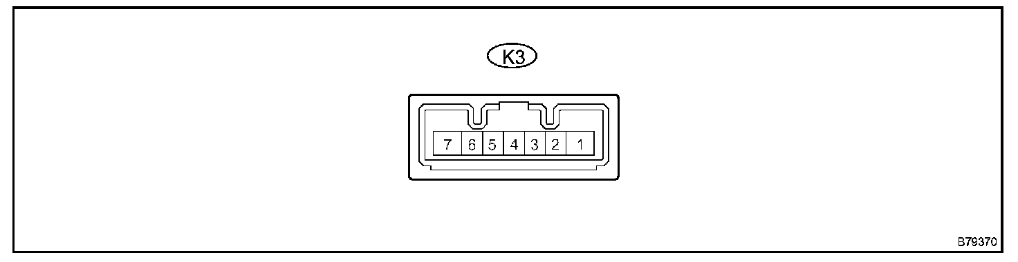
1. CHECK KEY SLOT
a. Disconnect the K3 key slot connector.
b. Measure the resistance of the wire harness side connector.

If the result is not as specified, there may be a malfunction on the wire harness side.
c. Reconnect the K3 key slot connector.
d. Measure the resistance and voltage of the connector.
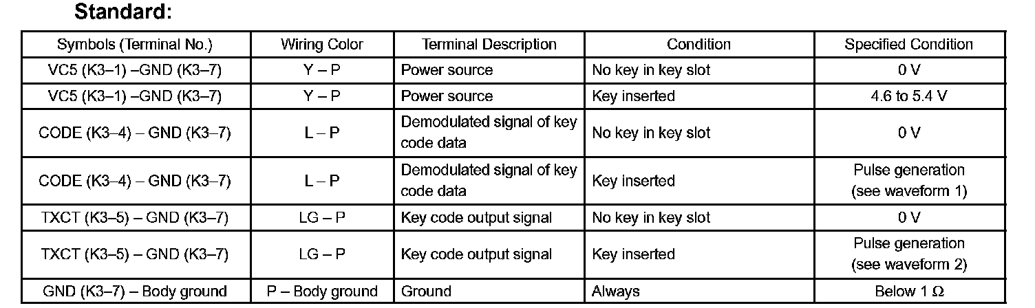
If the result is not as specified, key slot (amplifier) may have a malfunction.
Oscilloscope Waveforms Part 1:
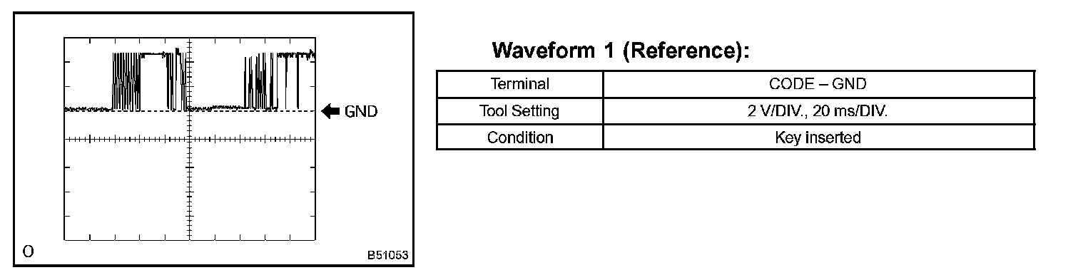
Oscilloscope Waveforms Part 2:
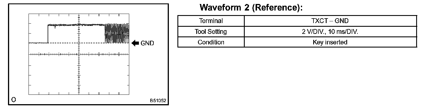
e. Inspect using an oscilloscope.
Terminals Of Control Module/Pinouts - Check Transponder Key ECU:
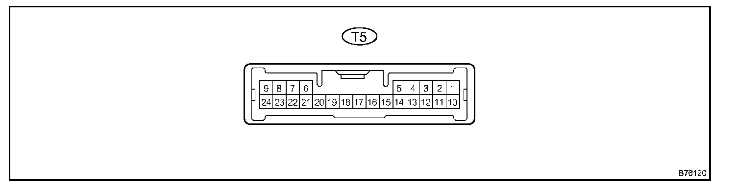
2. CHECK TRANSPONDER KEY ECU
a. Disconnect the T5 ECU connector.
b. Measure the resistance and voltage of the wire harness side connector.
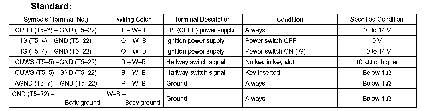
If the result is not as specified, there may be a malfunction on the wire harness side.
c. Reconnect the T5 ECU connector.
d. Measure the voltage of the connector.
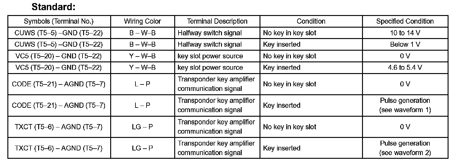

If the result is not as specified, ECU may have a malfunction.
Oscilloscope Waveforms:
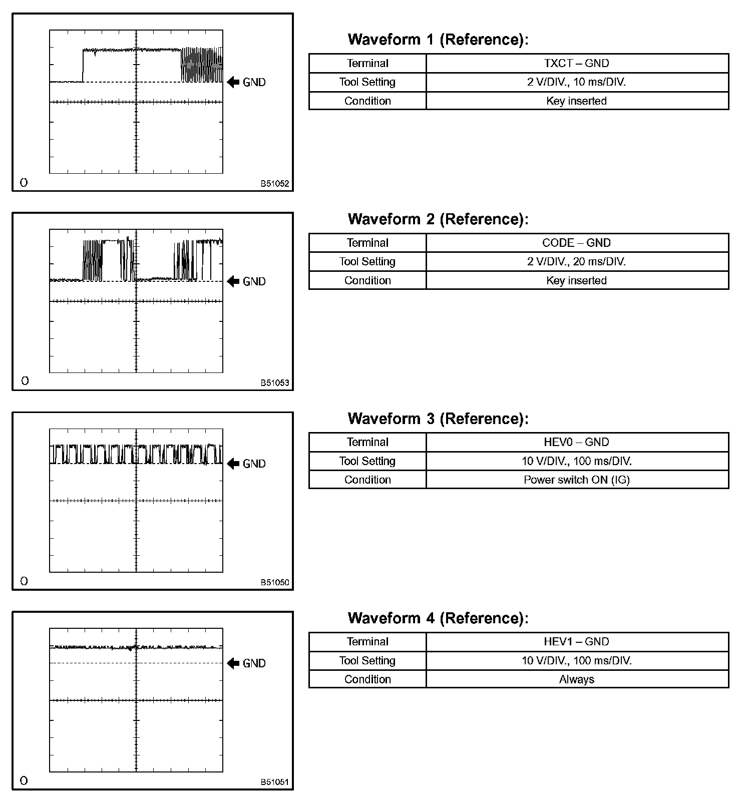
e. Inspect using an oscilloscope.
Terminals Of Control Module/Pinouts - Check Smart ECU:
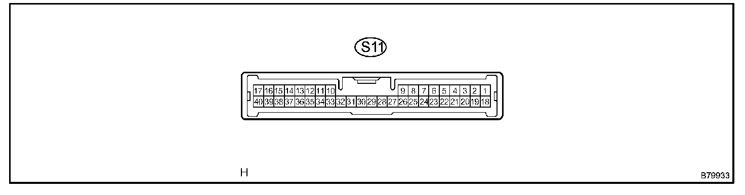
3. CHECK SMART ECU
a. Disconnect the S11 ECU connector.
b. Measure the voltage and resistance of the wire harness side connector.
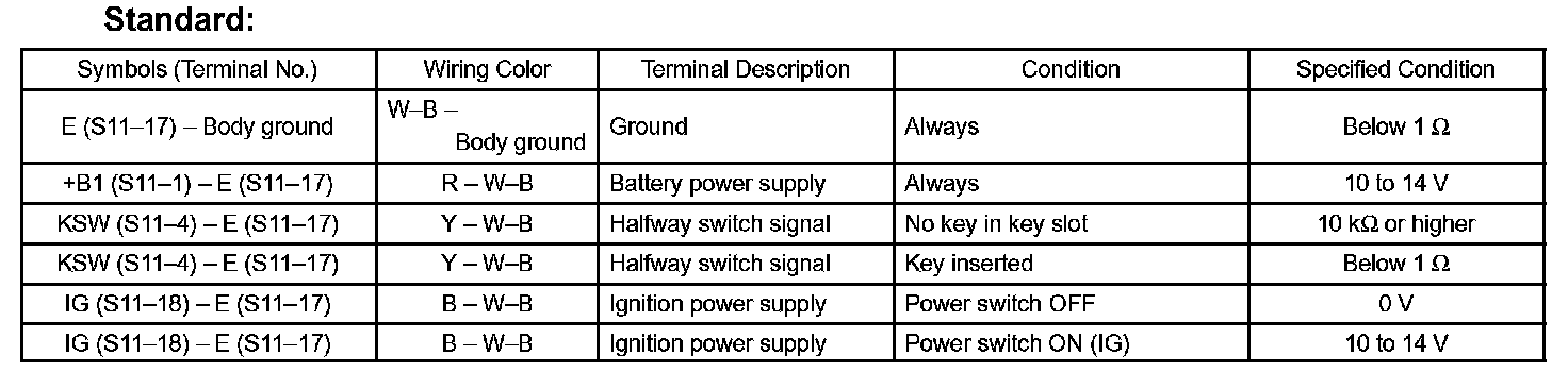
If the result is not as specified, there may be a malfunction on the wire harness side.
Terminals Of Control Module/Pinouts - Check Hybrid Vehicle Control ECU:
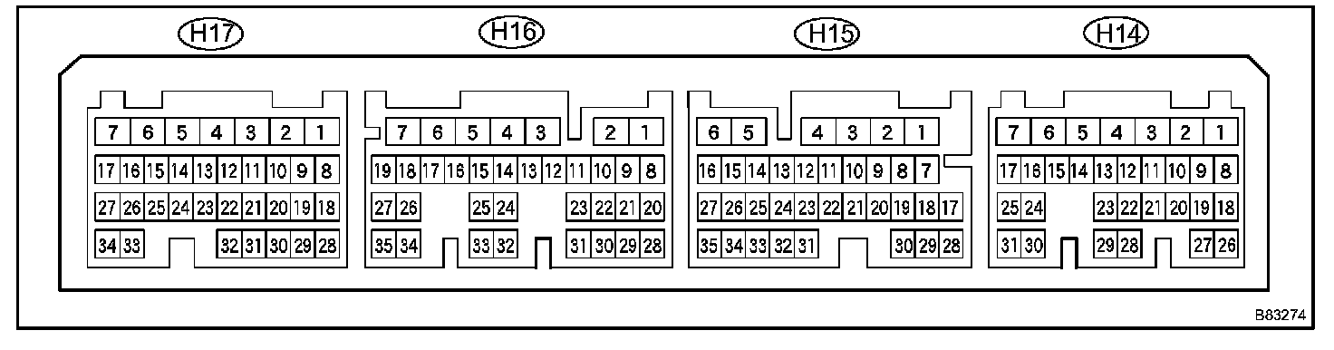
4. CHECK HYBRID VEHICLE CONTROL ECU
a. Measure the resistance and voltage of each terminal of the connectors.
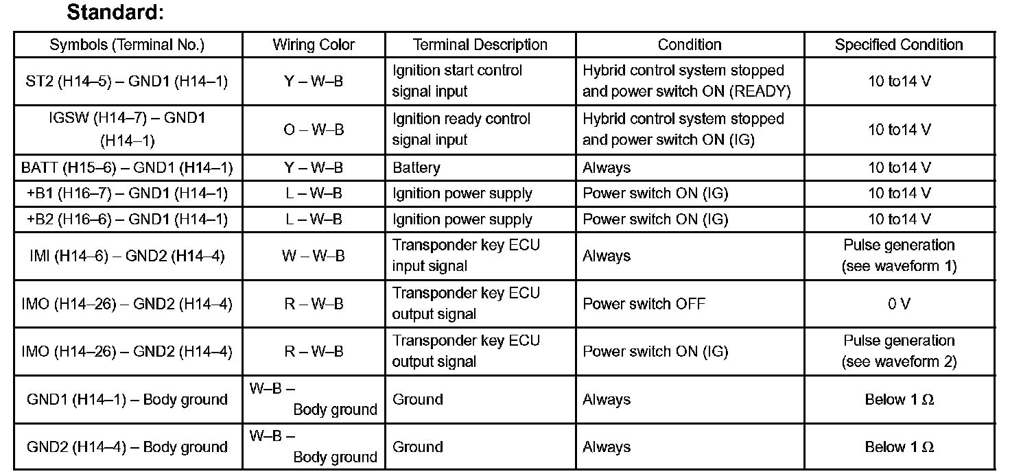
If the result is not as specified, ECM may have a malfunction.
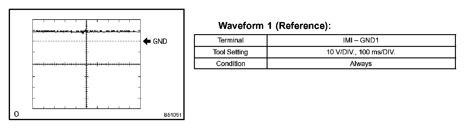
Oscilloscope Waveforms Part 1:
Oscilloscope Waveforms Part 2:
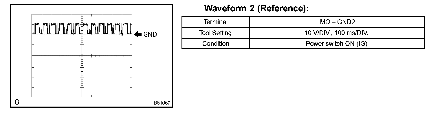
b. Inspect using an oscilloscope.