Smart Entry System
TERMINALS OF ECU1. CHECK SMART ECU
Terminals Of Control Module/Pinouts:
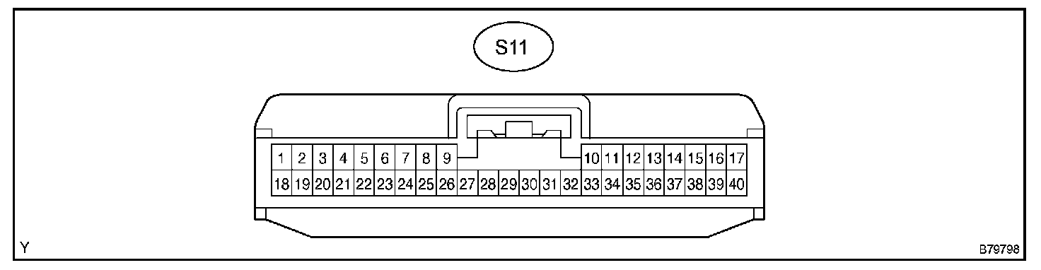
a. Disconnect the S11 ECU connector.
b. Measure the resistance and voltage of the wire harness side connector.
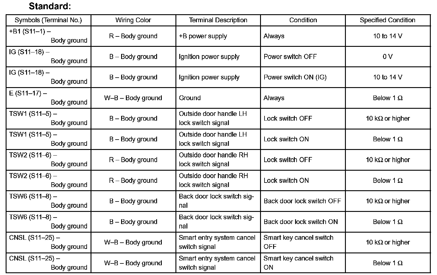
If the result is not as specified, there may be a malfunction on the wire harness side.
c. Reconnect the S11 ECU connector.
d. Measure the voltage and frequency of the connector.
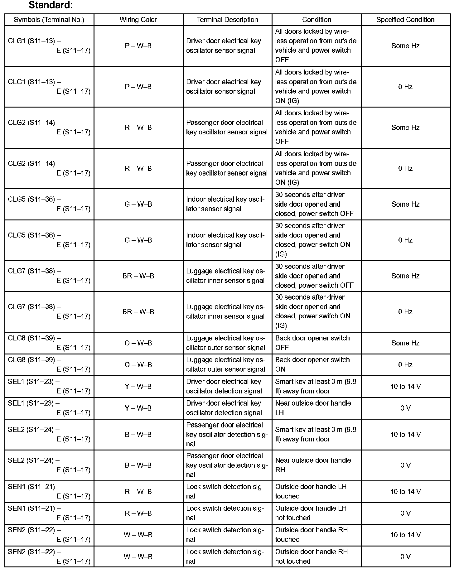
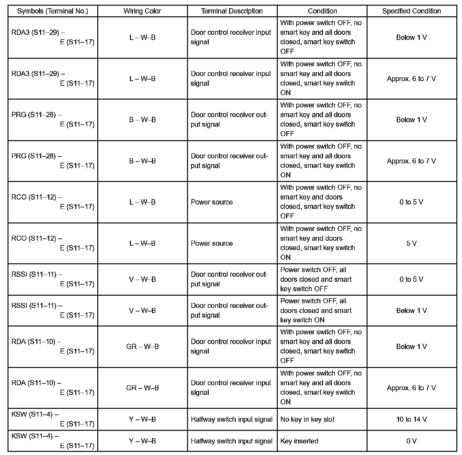
If the result is not as specified, the ECU may have a malfunction.
Terminals Of Control Module/Pinouts:
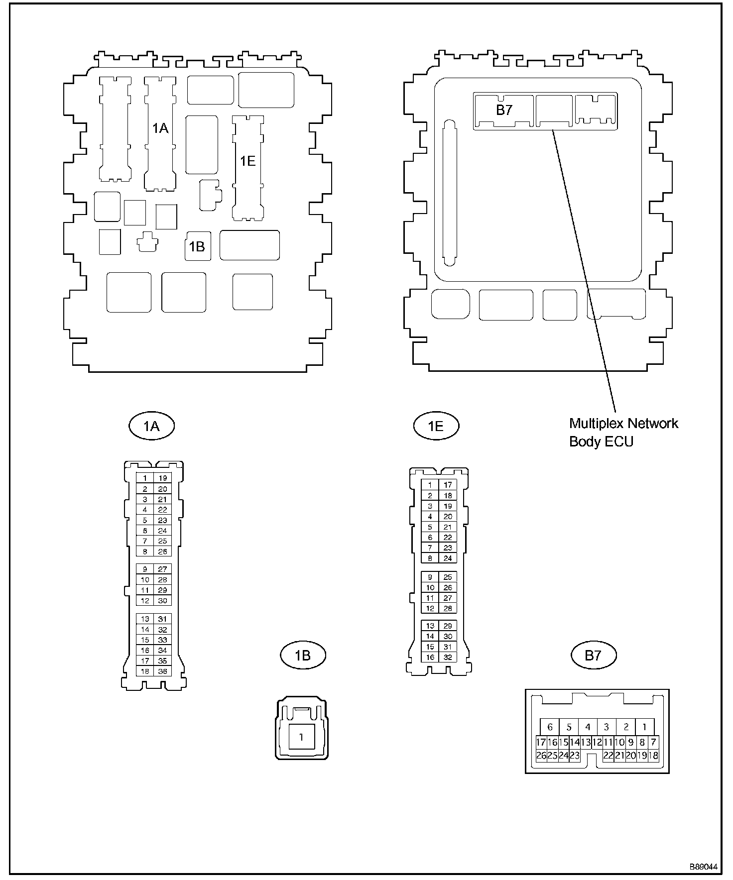
2. CHECK INSTRUMENT PANEL J/B ASSEMBLY (MULTIPLEX NETWORK BODY ECU)
a. Disconnect the 1A, 1B and 1E J/B connectors.
b. Measure the voltage and resistance of the wire harness side connector.
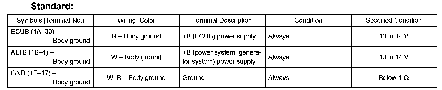
If the result is not as specified, there may be a malfunction on the wire harness side.
c. Reconnect the 1A, 1B and 1E J/B ECU connectors.
d. Measure the voltage of the connectors.
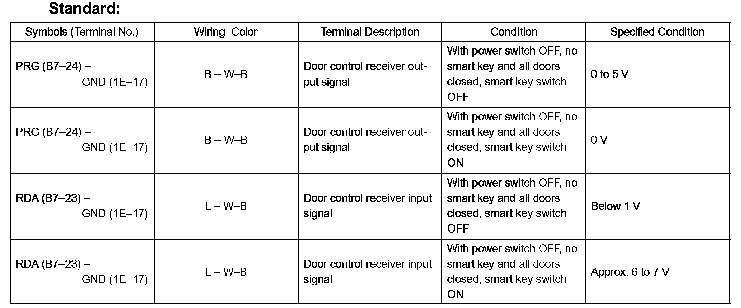
If the result is not as specified, the body ECU may have a malfunction.
3. CHECK TRANSPONDER KEY ECU
Terminals Of Control Module/Pinouts - Check Transponder Key ECU:
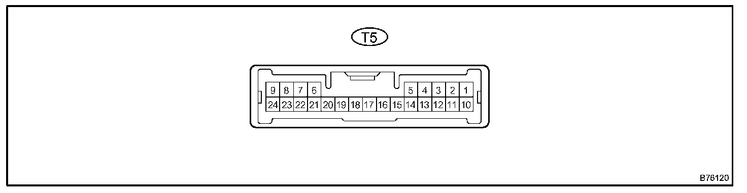
a. Disconnect the T5 ECU connector.
b. Measure the resistance and voltage of the wire harness side connector.
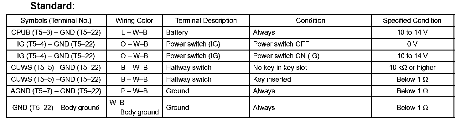
If the result is not as specified, there may be a malfunction on the wire harness side.
c. Reconnect the T5 ECU connector.
d. Measure the voltage of the connector.
e. Inspect using an oscilloscope.
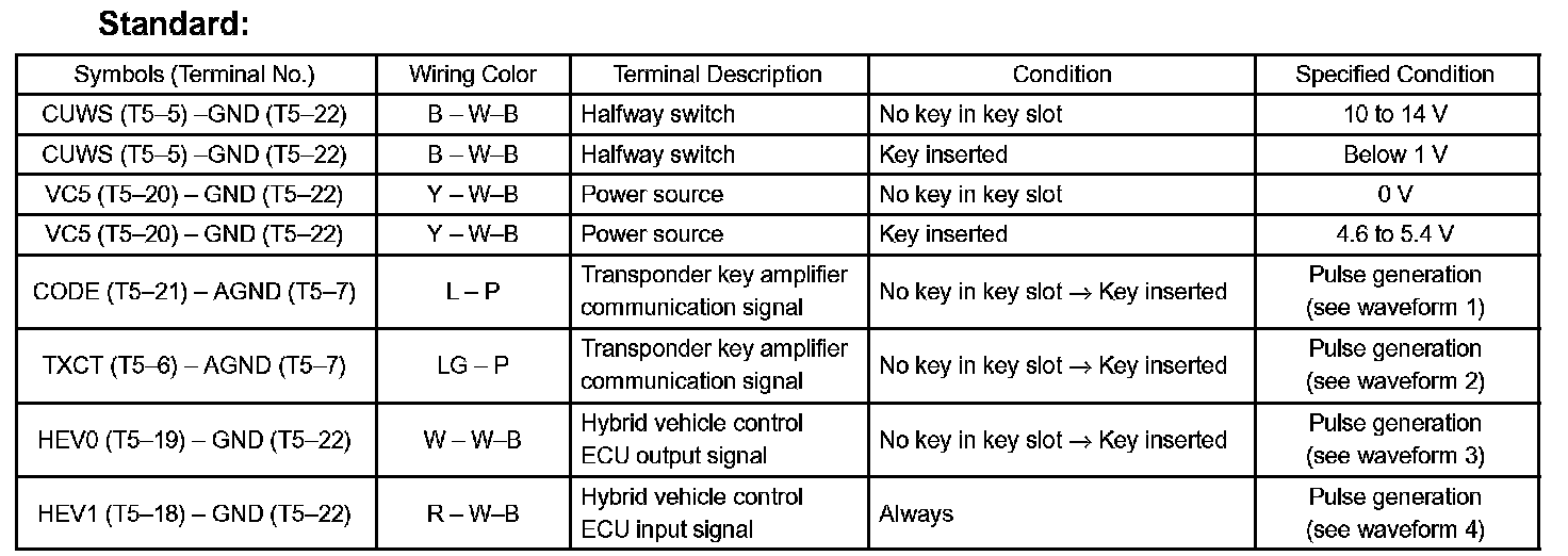
Oscilloscope Waveforms:
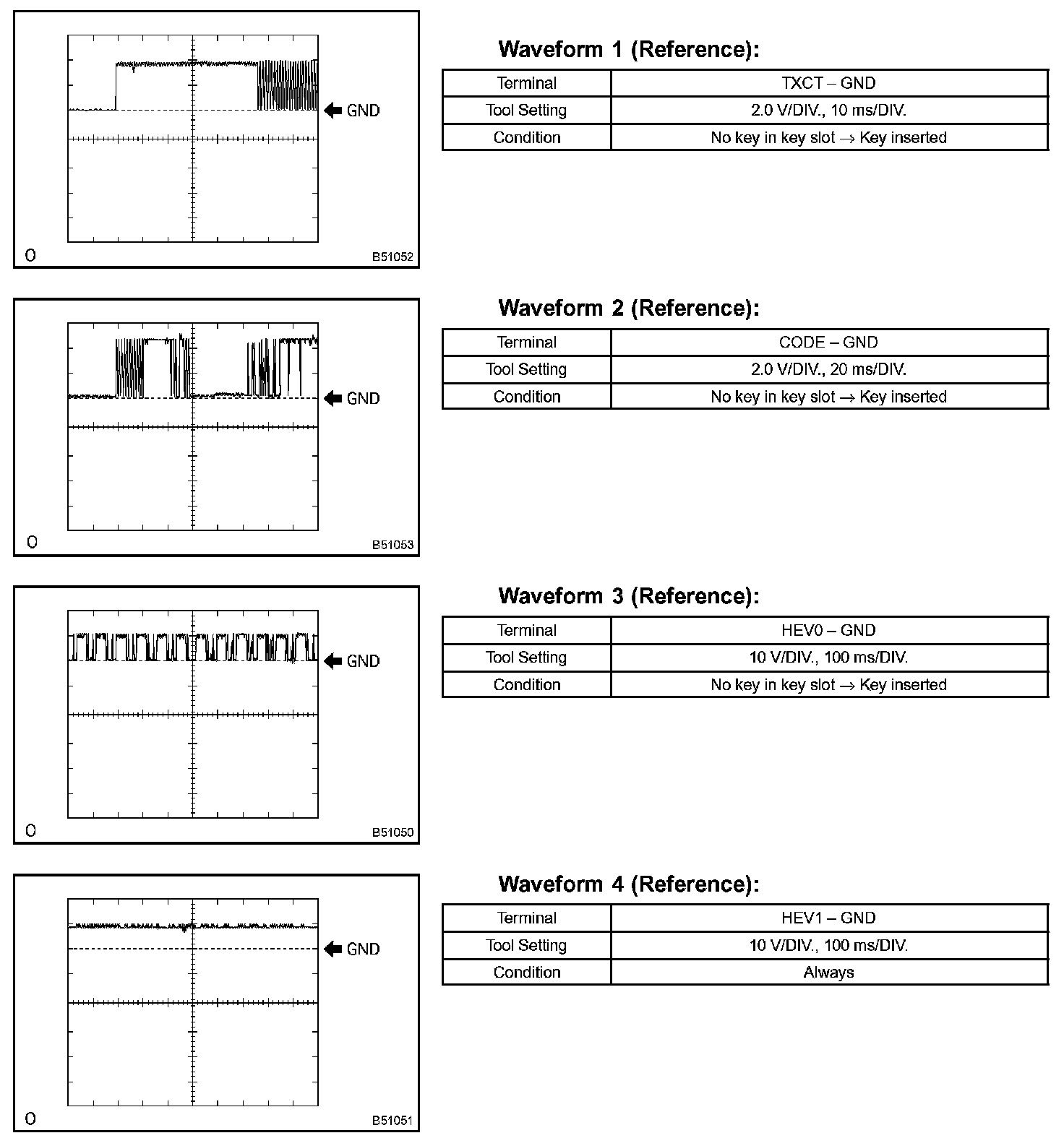
If the result is not as specified, the ECU may have a malfunction.