Brake Control Power Supply Assembly
BRAKE CONTROL POWER SUPPLY ASSEMBLYREPLACEMENT
1. REMOVE REAR SEAT CUSHION ASSEMBLY
2. REMOVE DECK TRIM SIDE PANEL ASSEMBLY RH
HINT: Refer to the procedures from the removal of the rear door scuff plate RH up until the removal of the deck trim side panel assembly RH.
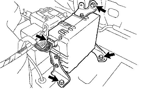
3. REMOVE BRAKE CONTROL POWER SUPPLY ASSEMBLY
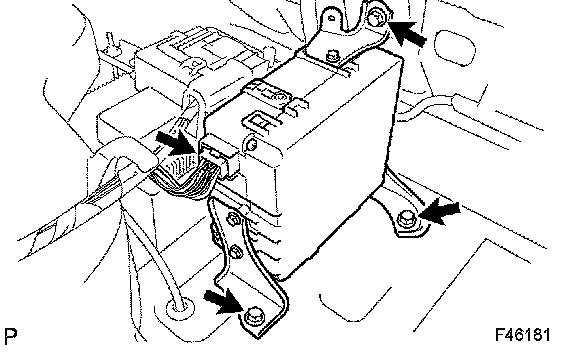
a) Disconnect the connector and remove the 3 bolts and the brake control power supply assembly.
4. INSTALL BRAKE CONTROL POWER SUPPLY ASSEMBLY
a) Install the brake control power supply assembly with the 3 bolts.
Torque: 19 Nm (194 kgf-cm, 14 ft. lbs.)
b) Connect the connector to the brake control power supply assembly.
5. INSTALL DECK TRIM SIDE PANEL ASSEMBLY RH
6. INSTALL REAR SEAT CUSHION ASSEMBLY
7. CHECK AND CLEAR DTC