Electronic Brake Control Module: Testing and Inspection
TERMINALS OF ECU1. CHECK BATTERY VOLTAGE
a. Measure the battery voltage.
Standard: 10 to 14 V
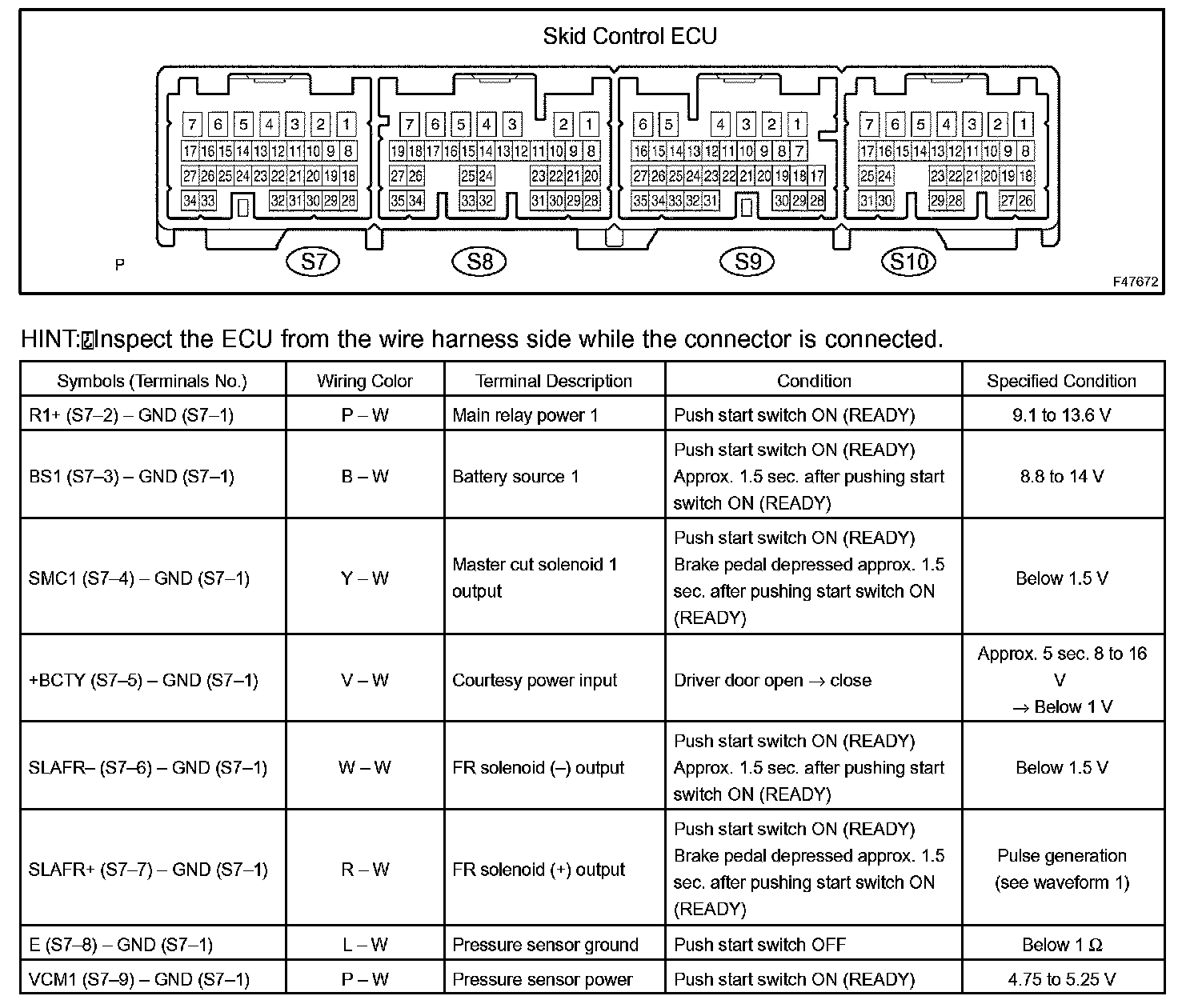
2. SKID CONTROL ECU ASSEMBLY INSPECTION
a. Measure the voltage between each terminal or between each terminal and the body ground.
b. Connect the hand-held tester to the DLC3, and check the communication condition with the skid control ECU.
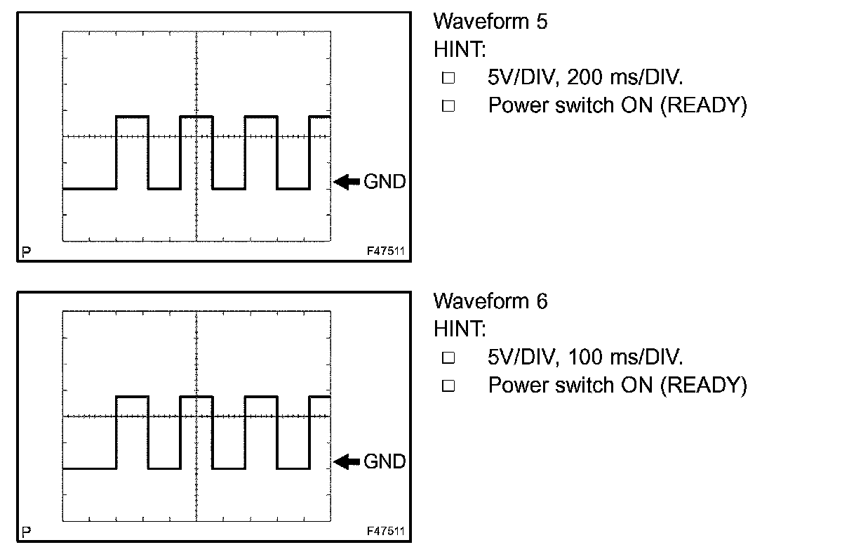
c. Using an oscilloscope, check that the pulse generates between each terminal or between each terminal and the body ground.
NOTE:
- Inspection should be performed from the back of the connector with the connector connected to the skid control ECU.
- The voltage between terminals of the brake actuator assembly may become 0 V due to the fail safe function when the ECB warning light comes on (malfunctioning).
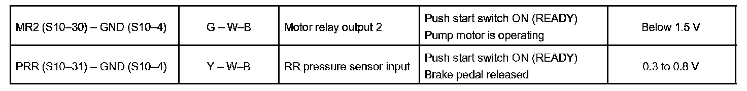
Terminals Of Control Module/Pinouts Part 1:
Terminals Of Control Module/Pinouts Part 2:
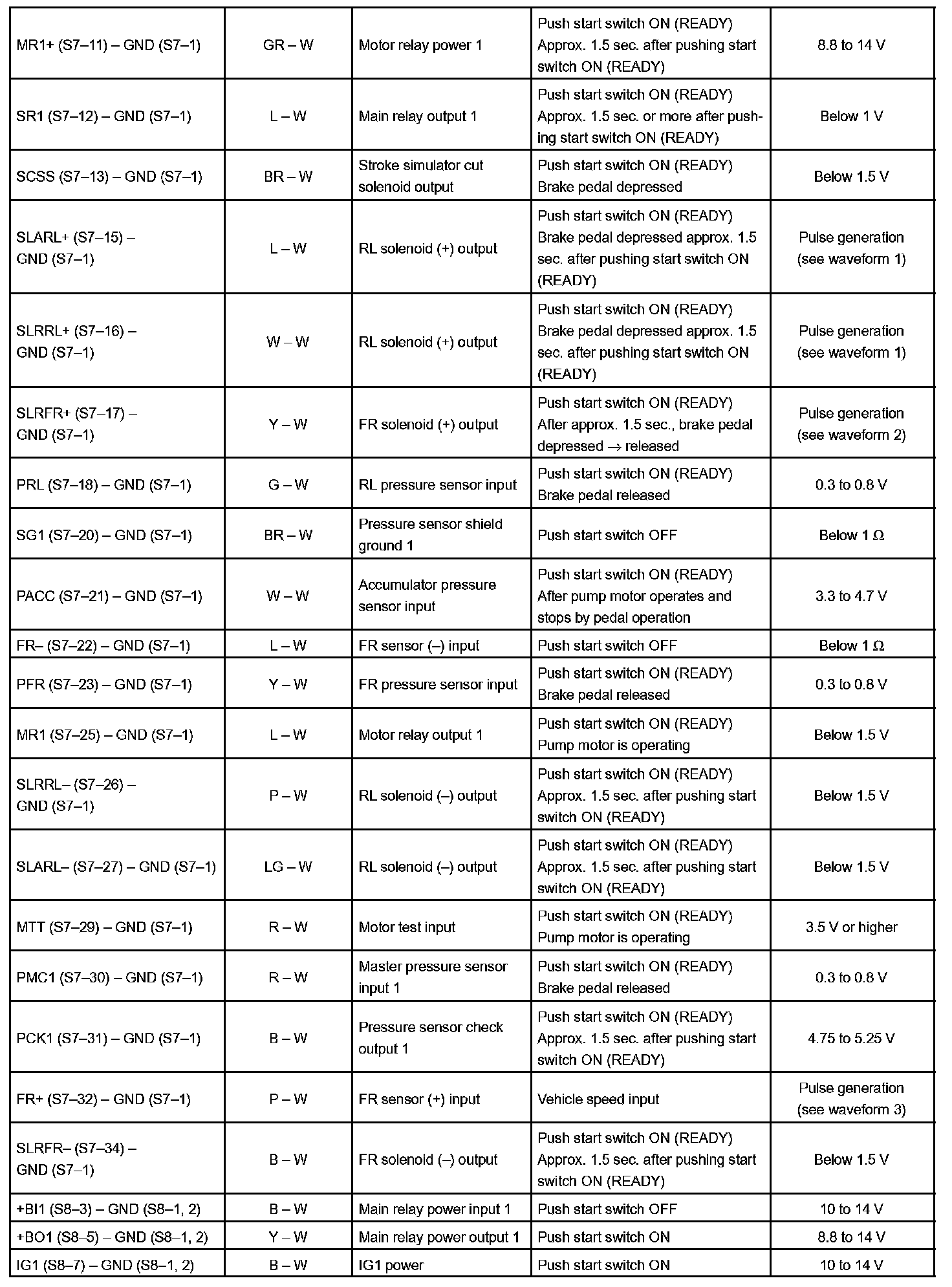
Terminals Of Control Module/Pinouts Part 3:
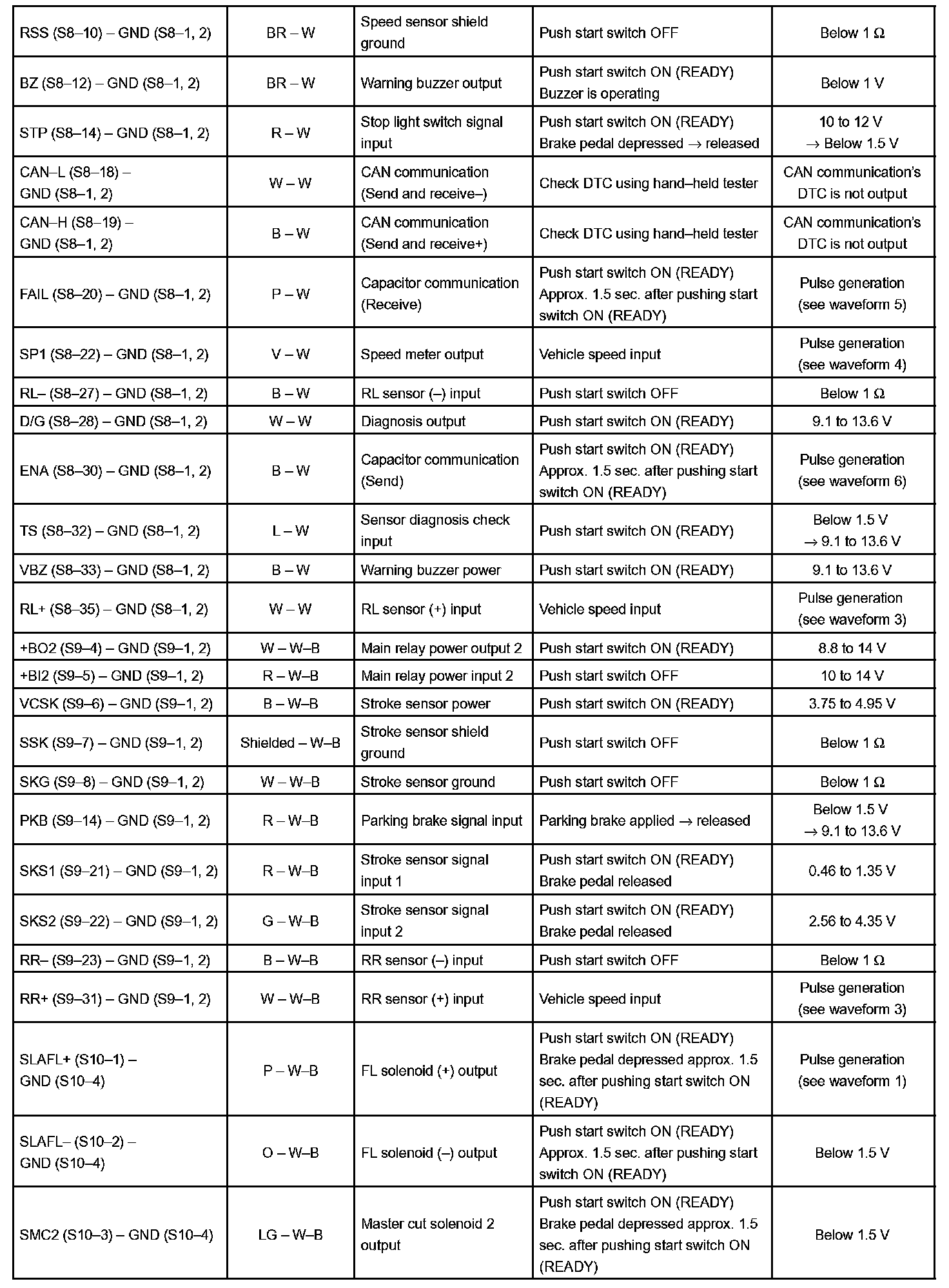
Terminals Of Control Module/Pinouts Part 4:
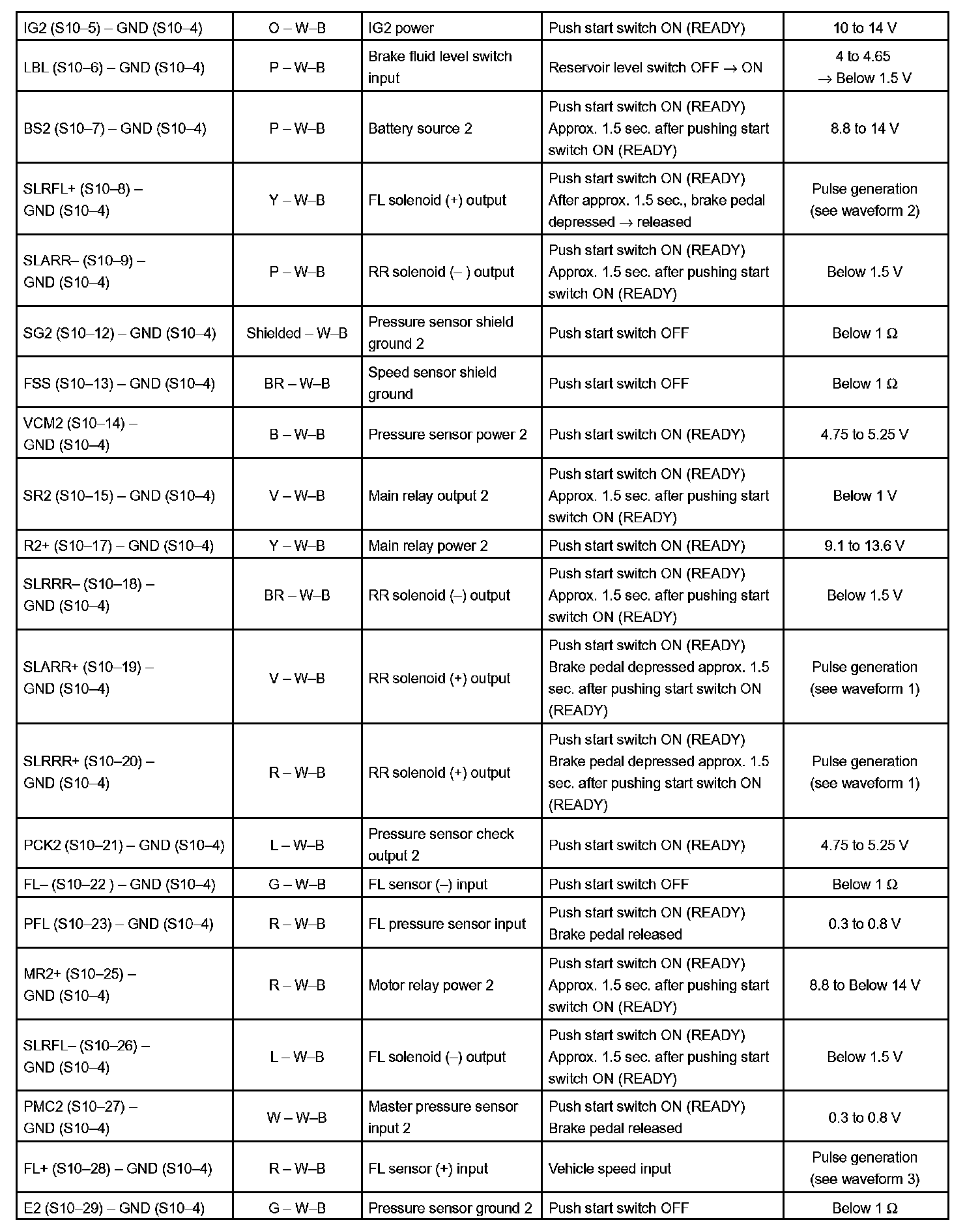
Terminals Of Control Module/Pinouts Part 5:
Oscilloscope Waveforms Part 1:
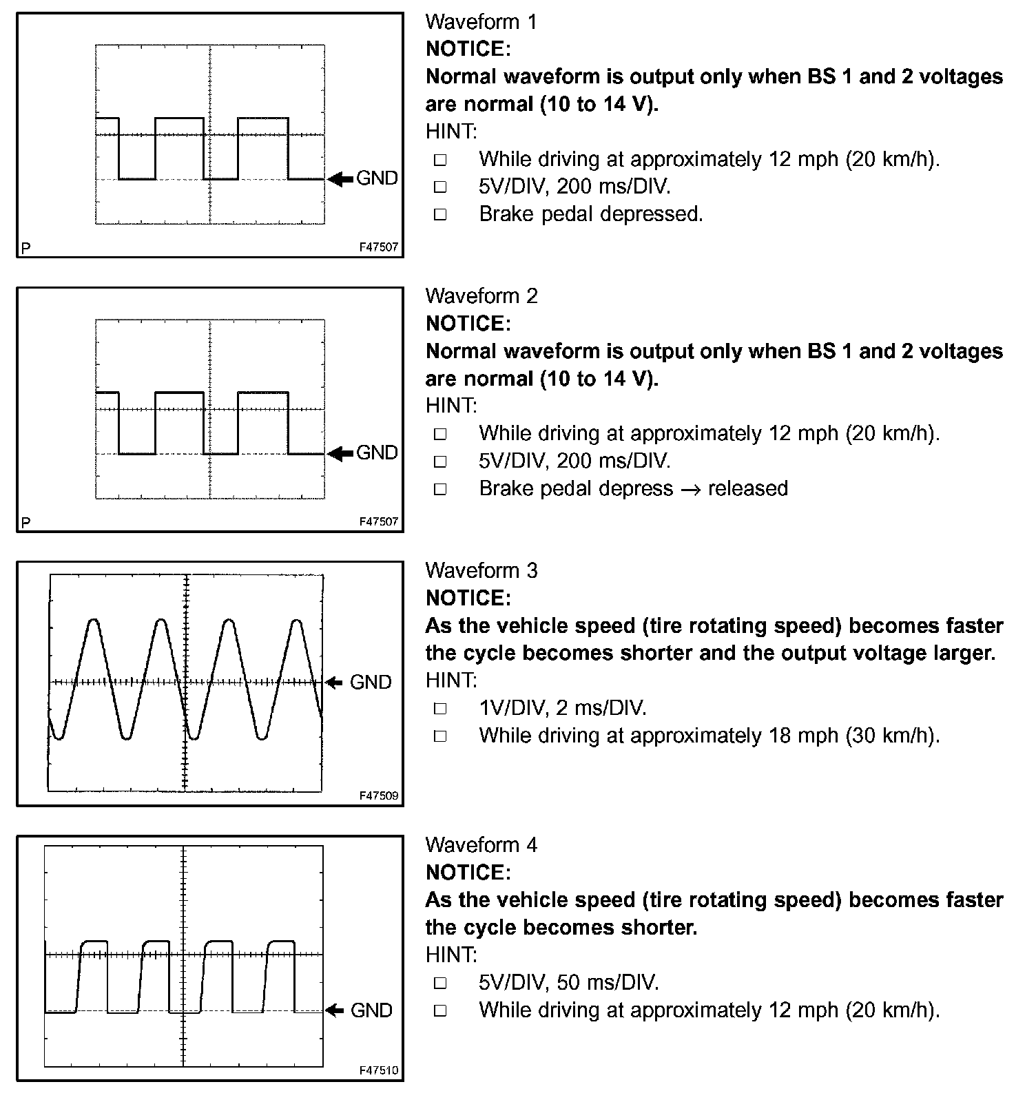
Oscilloscope Waveforms Part 2:
SKID CONTROL ECU