Daytime Running Light Relay Circuit
DAYTIME RUNNING LIGHT RELAY CIRCUITCIRCUIT DESCRIPTION
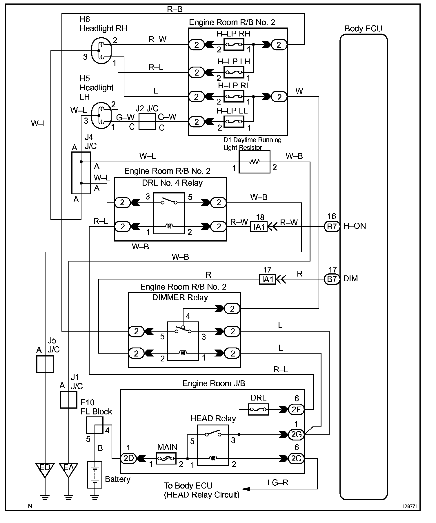
Power is supplied to the DIMMER and DRL No. 4 relays when the HEAD relay is turned on.
The HEAD relay turns on by turning the light control switch to the TAIL or HEAD position.
The DIMMER relay turns on by turning the headlight dimmer switch to the LOW, HIGH, or FLASH position.
The body ECU determines the light control switch position and turns on the DRL No. 4 and DIMMER relays.
The DRL No. 4 relay and the daytime running light resistor are parallel circuits. If the light control switch is OFF, electric current flows to body ground via the resistor instead of driving the DRL No. 4 relay. The headlights come on and dim according to the amount of resistance.
Wiring Diagram:
Step 1 - 2:
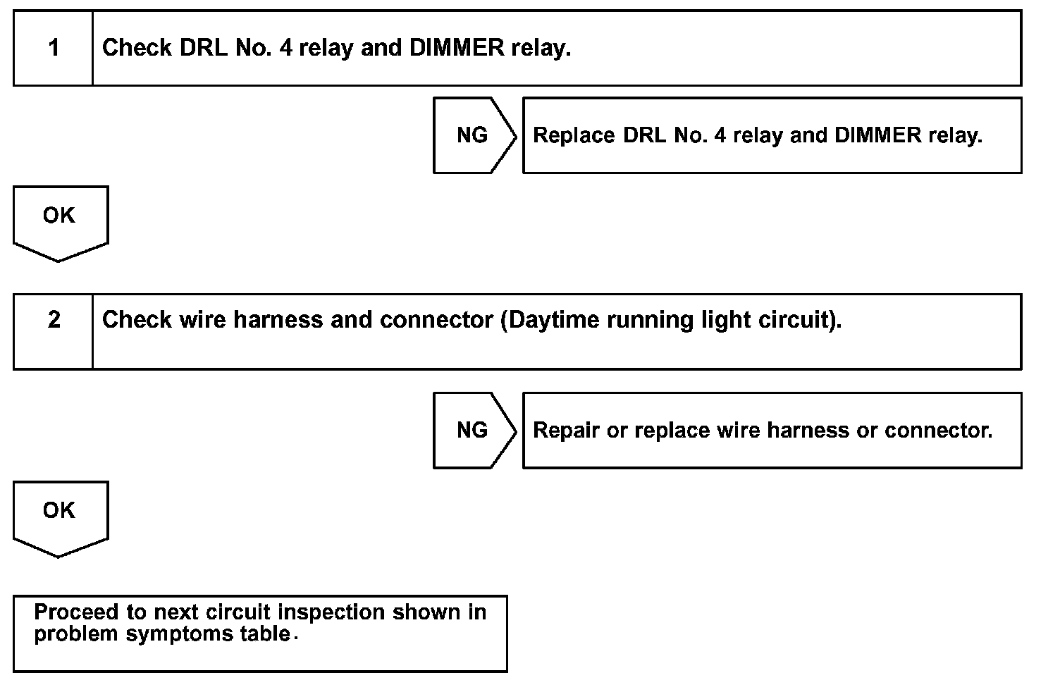
INSPECTION PROCEDURE