Multiplex Communication System
TERMINALS OF ECU1. CHECK MULTIPLEX NETWORK GATEWAY ECU
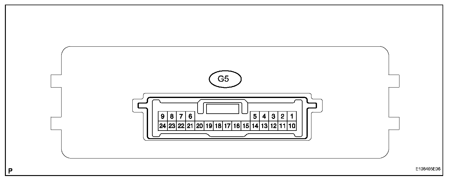
a. Disconnect the G5 ECU connector.
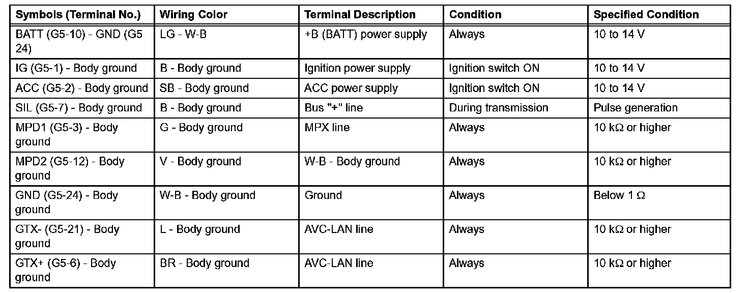
b. Measure the voltage and resistance of the wire harness side connector.
If the result is not as specified, there may be a malfunction on the wire harness side.
2. CHECK MULTIPLEX NETWORK BODY ECU
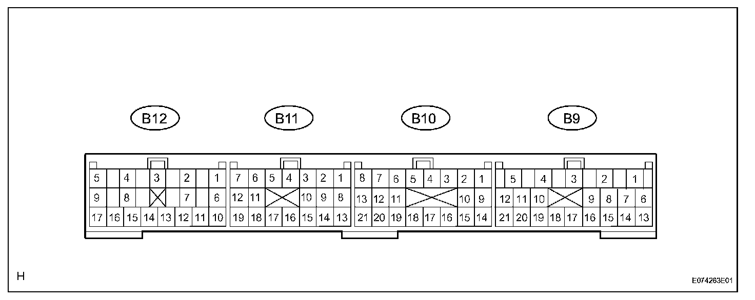
a. Disconnect the B9, B10 and B12 ECU connectors.
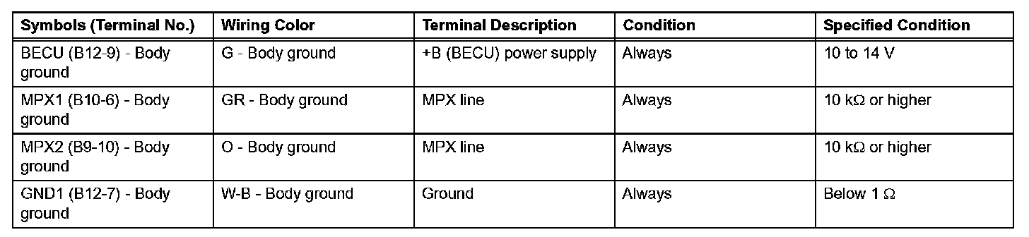
b. Measure the resistance and voltage of the wire harness side connectors.
If the result is not as specified, there may be a malfunction on the wire harness side.
3. CHECK AIR CONDITIONING AMPLIFIER (A/C ECU)
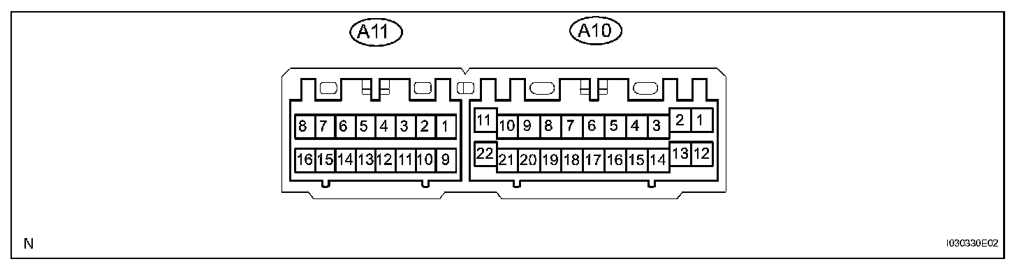
a. Disconnect the A10 and A11 amplifier connectors.
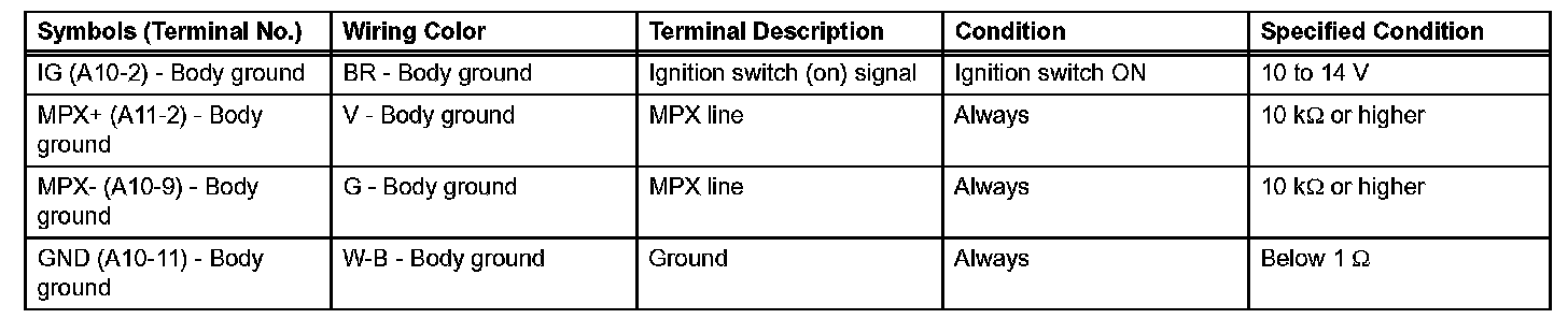
b. Measure the voltage and resistance of the wire harness side connectors.
If the result is not as specified, there may be a malfunction on the wire harness side.
4. CHECK CENTER AIRBAG SENSOR ASSEMBLY
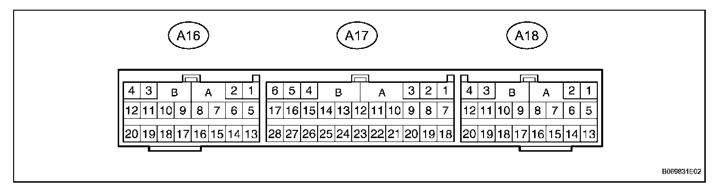
a. Disconnect the A17 sensor connector.

b. Measure the voltage and resistance of the wire harness side connector.
If the result is not as specified, there may be a malfunction on the wire harness side.
5. CHECK COMBINATION METER ASSEMBLY (METER ECU)

a. Disconnect the C11 and C12 meter connectors.
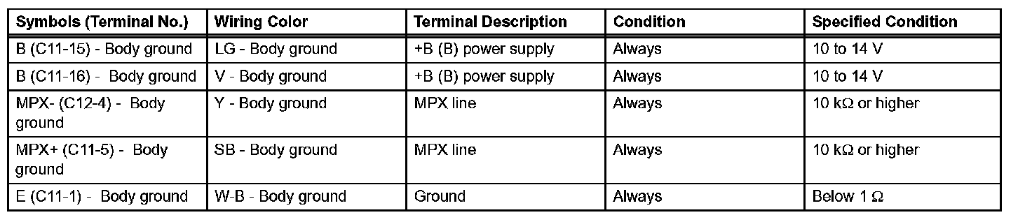
b. Measure the voltage and resistance of the wire harness side connectors.
If the result is not as specified, there may be a malfunction on the wire harness side.
6. CHECK SLIDING ROOF DRIVE GEAR (SLIDING ROOF CONTROL ECU)

a. Disconnect the S20 driver gear connector.

b. Measure the voltage and the resistance of the wire harness side connector.
If the result is not as specified, there may be a malfunction on the wire harness side.
7. CHECK MULTIPLEX NETWORK MASTER SWITCH
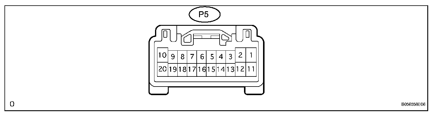
a. Disconnect the P5 switch connector.
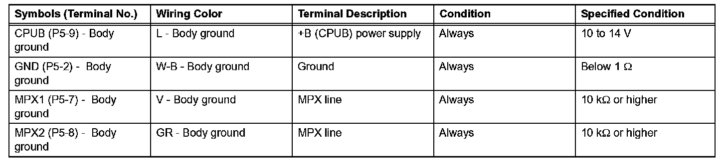
b. Measure the voltage and resistance of the wire harness side connector.
If the result is not as specified, there may be a malfunction on the wire harness side.
8. CHECK THEFT DETERRENT ECU
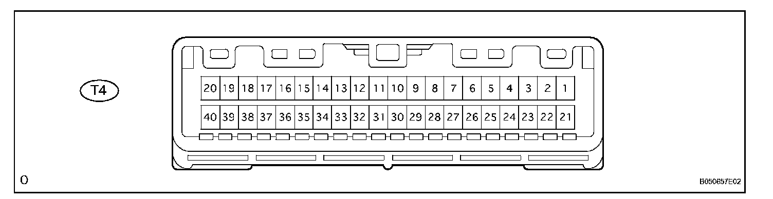
a. Disconnect the T4 ECU connector.

b. Measure the resistance and voltage of the wire harness side connector.
If the result is not as specified, there may be a malfunction on the wire harness side.