Engine Unit, Inspection
ENGINE UNITINSPECTION
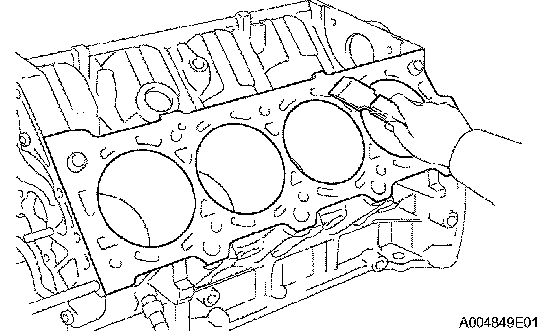
1. INSPECT CYLINDER BLOCK SUB-ASSEMBLY
a) Clean the cylinder block.
1) Using a gasket scraper, remove all the gasket material from the top surface of the cylinder block.
2) Using a soft brush and solvent, thoroughly clean the cylinder block.
NOTICE: If the cylinder is washed at high temperatures, the cylinder liner sticks out beyond the cylinder block. Always wash the cylinder block at a temperature of 45°C (113°F) or less.
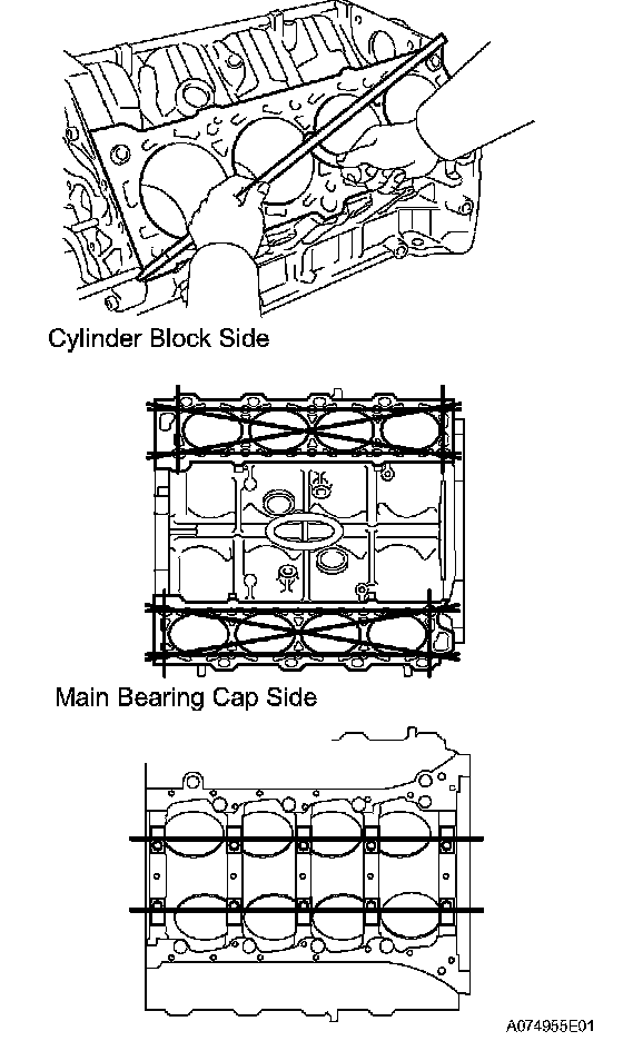
b) Inspect for flatness.
1) Using a precision straightedge and feeler gauge, measure the surfaces contacting the cylinder head and main bearing cap for warpage.
Maximum warpage: 0.07 mm (0.0028 inch)
If the warpage is greater than the maximum, replace the cylinder block.
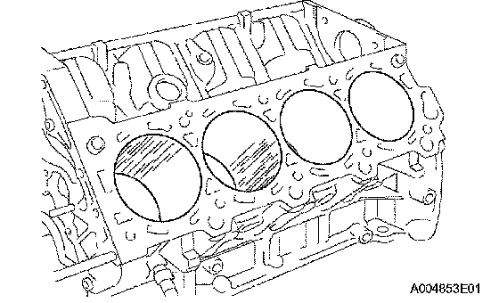
c) Visually check the cylinder for vertical scratches. If deep scratches are present, rebore all 8 cylinders and replace all 8 pistons. If necessary, replace the cylinder block.
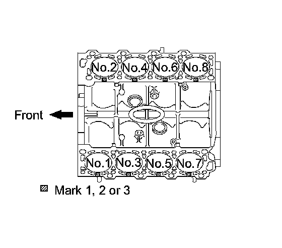
d) Inspect the cylinder bore diameter.
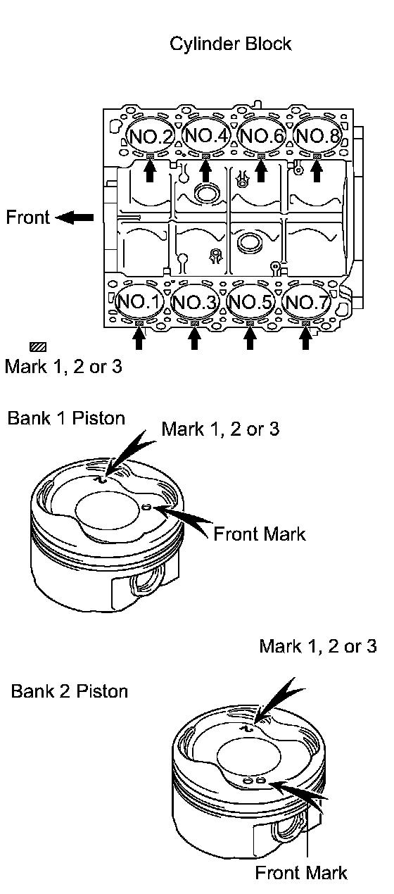
HINT: There are 3 sizes of the standard cylinder bore diameter, marked "1", "2" and "3" accordingly The mark is stamped on the top of the cylinder block.
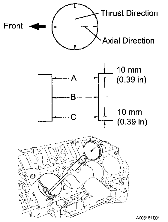
1) Using a cylinder gauge, measure the cylinder bore diameter at positions A, B and C in the thrust and axial directions.
Standard diameter:
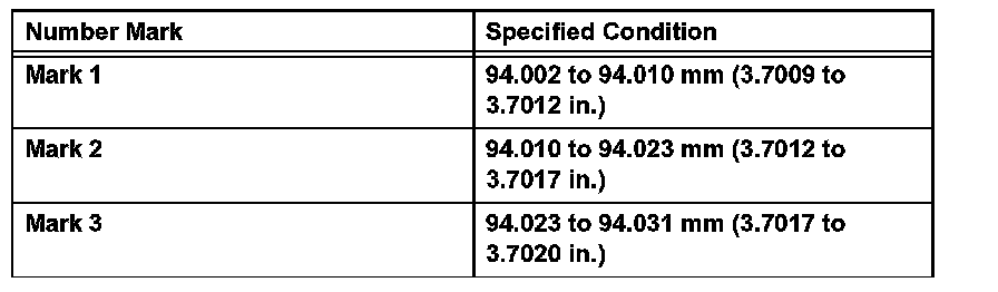
Maximum diameter: 94.230 mm (3.7098 inch)
If the diameter is greater than the maximum, rebore all 8 cylinders and replace all 8 pistons. If necessary, replace the cylinder block.
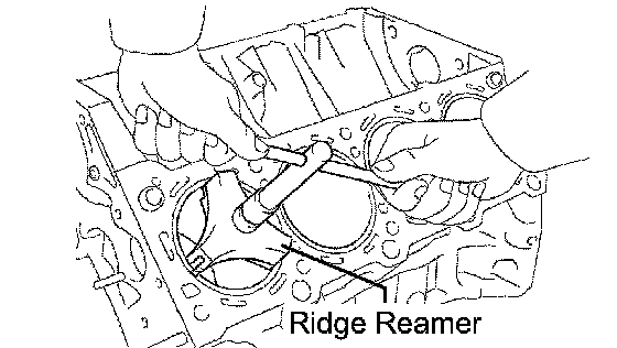
e) Remove the cylinder ridge.
HINT: If the wear is less than 0.2 mm (0.008 inch), using a ridge reamer, grind the top of the cylinder.
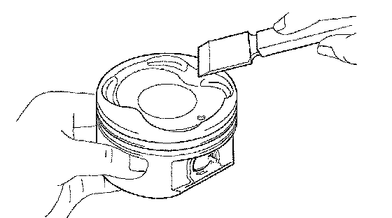
2. INSPECT PISTON SUB-ASSEMBLY WITH PIN
a) Clean the piston.
1) Using a gasket scraper, remove the carbon from the piston top.
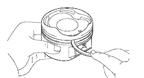
2) Using a groove cleaning tool or broken ring, clean the piston ring grooves.
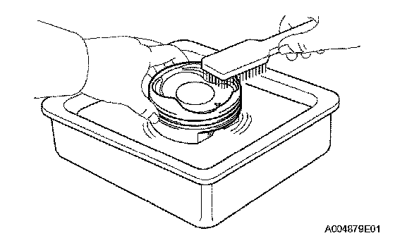
3) Using solvent and a brush, thoroughly clean the piston.
NOTICE: Do not use a wire brush.
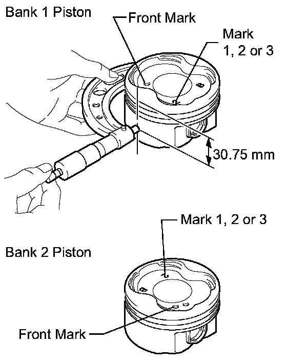
b) Inspect the piston oil clearance.
HINT: There are 3 standard diameter sizes, marked "1" "2" and "3". The mark is stamped on the piston top.
1) Using a micrometer, measure the piston diameter at right angles to the piston pin center line, 30.75 mm (1.2106 inch) from the piston head.
Standard piston diameter:
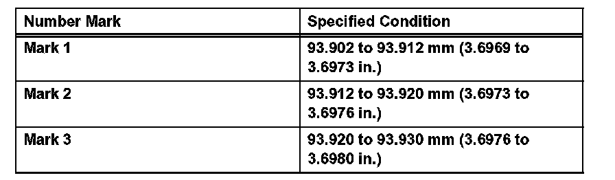
2) Measure the cylinder bore diameter in the thrust directions.
3) Subtract the piston diameter measurement from the cylinder bore diameter measurement.
Standard oil clearance: 0.090 to 0.111 mm (0.0035 to 0.0044 inch)
Maximum oil clearance: 0.13 mm (0.0051 inch)
If the oil clearance is greater than the maximum, replace all 8 pistons and rebore all 8 cylinders. If necessary, replace the cylinder block.
HINT: Use a new cylinder block:
^ Use a piston with the same number mark as the cylinder diameter marked on the cylinder block.
^ The shape of the piston varies for the LH and RH banks. The LH piston is marked with 1 cavity and "2", the RH piston with 2 cavities and "2".
c) Inspect the piston pin fit.
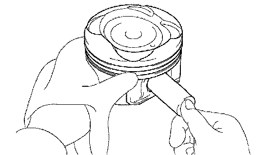
1) Heat the piston to approximately 60°C (140°F), and push the piston pin into the piston pin hole with your thumb.
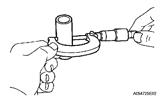
d) Using a micrometer, measure the piston pin diameter.
Standard piston pin diameter: 21.997 to 22.009 mm (0.8660 to 0.8664 inch)
3. INSPECT PISTON RING SET
a) Inspect the piston ring groove clearance.
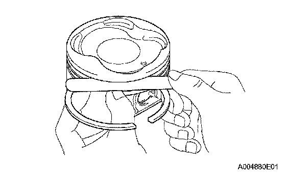
1) Using a feeler gauge, measure the clearance between a new piston ring and the wall of the ring groove.
Standard ring groove clearance:
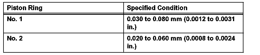
If the clearance is not as specified, replace the piston.
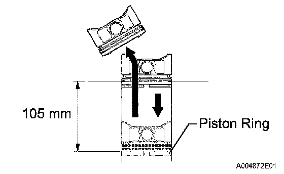
b) Inspect the piston ring end gap.
1) Insert the piston ring into the cylinder bore.
2) Using a piston, push the piston ring a little beyond the bottom of the ring travel, 105 mm (4.13 inch) from the top of the cylinder block.
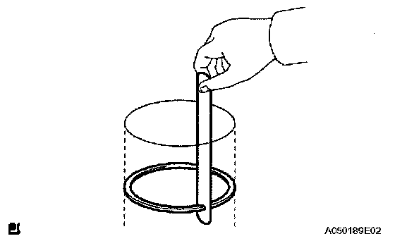
3) Using a feeler gauge, measure the end gap.
Standard end gap:
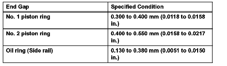
Maximum end gap:
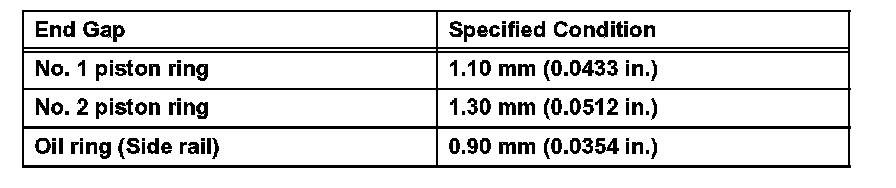
If the end gap is greater than the maximum, replace the piston ring. If the end gap is greater than the maximum even with a new piston ring, rebore all 8 cylinders or replace the cylinder block sub-assembly.
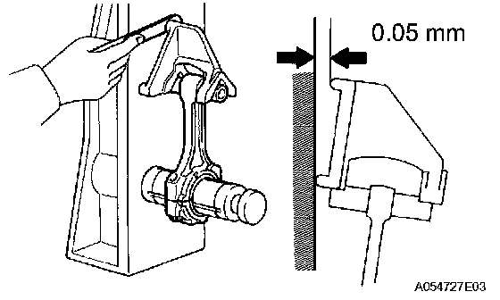
4. INSPECT CONNECTING ROD SUB-ASSEMBLY
a) Using a rod aligner and feeler gauge, check the connecting rod alignment.
1) Check if the connecting rod is bent.
Maximum bend: 0.05 mm (0.0020 inch) per 100 mm (3.94 inch)
If the bend is greater than the maximum, replace the connecting rod.
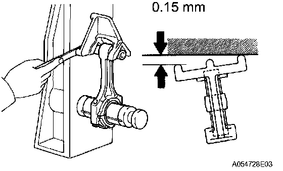
2) Check if the connecting rod is twisted.
Maximum twist: 0.15 mm (0.0059 inch) per 100 mm (3.94 inch)
If the twist is greater than the maximum, replace the connecting rod sub-assembly.
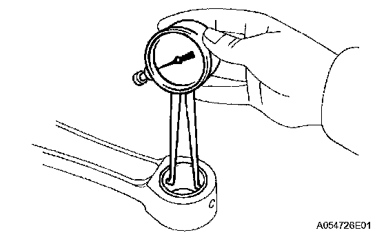
5. INSPECT PISTON PIN OIL CLEARANCE
a) Inspect the piston pin oil clearance.
1) Using a caliper gauge, measure the inside diameter of the connecting rod bush.
Standard bush inside diameter: 22.005 to 22.014 mm (0.8663 to 0.8667 inch)
If the bushing inside diameter is not as specified, check the oil clearance.
2) Subtract the piston pin diameter measurement from the bush inside diameter measurement.
Standard oil clearance: 0.005 to 0.011 mm (0.0002 to 0.0004 inch)
Maximum oil clearance: 0.05 mm (0.0020 inch)
If the oil clearance is greater than the maximum, replace the bush. If necessary, replace the piston and piston pin with a new piston and pin set.
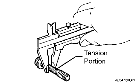
6. INSPECT CONNECTING ROD BOLT
a) Using a vernier caliper, measure the tension portion of the connecting rod bolt.
Standard diameter: 7.200 to 7.300 mm (0.2835 to 0.2874 inch)
Maximum diameter: 7.00 mm (0.2756 inch)
If the diameter is less than the minimum, replace the bolt.
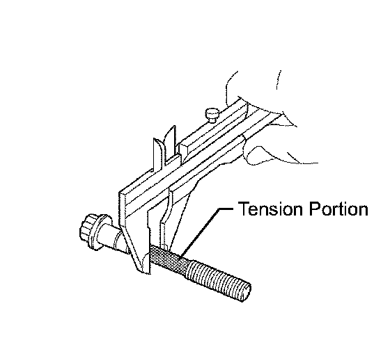
7. INSPECT CRANKSHAFT BEARING CAP BOLT
a) Using a vernier caliper, measure the tension portion diameter of the main bearing cap bolt.
Standard diameter: 10.760 to 10.970 mm (0.4236 to 0.4319 inch)
Maximum diameter: 10.40 mm (0.4094 inch)
If the diameter is less than the minimum, replace the cap bolt.
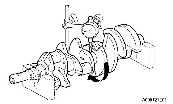
8. INSPECT CRANKSHAFT
a) Inspect for circle runout.
1) Place the crankshaft on V-blocks.
2) Using a dial indicator, measure the circle runout at the center journal.
Maximum circle runout: 0.04 mm (0.0016 inch)
If the circle runout is greater the maximum, replace the crankshaft.
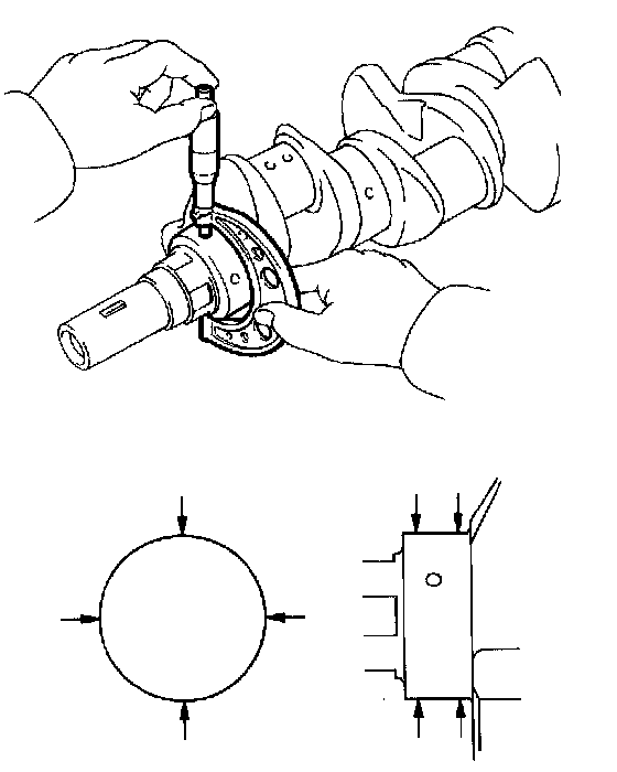
b) Inspect the main journals and crank pins.
1) Using a micrometer, measure the diameter of each main journal and crank pin.
Main journal diameter: 66.988 to 67.000 mm (2.6373 to 2.6378 inch)
Standard crank pin diameter: 51.982 to 52.000 mm (2.0465 to 2.0472 inch)
If the diameter is not as specified, check the oil clearance. If necessary, replace the crankshaft.
2) Check each main journal and crank pin for taper and out of round as shown in the illustration.
Maximum taper and out of round: 0.02 mm (0.0008 inch)
If the taper and out of round is greater than the maximum, replace the crankshaft.