Part 1
ENGINE UNITEngine Unit Components:
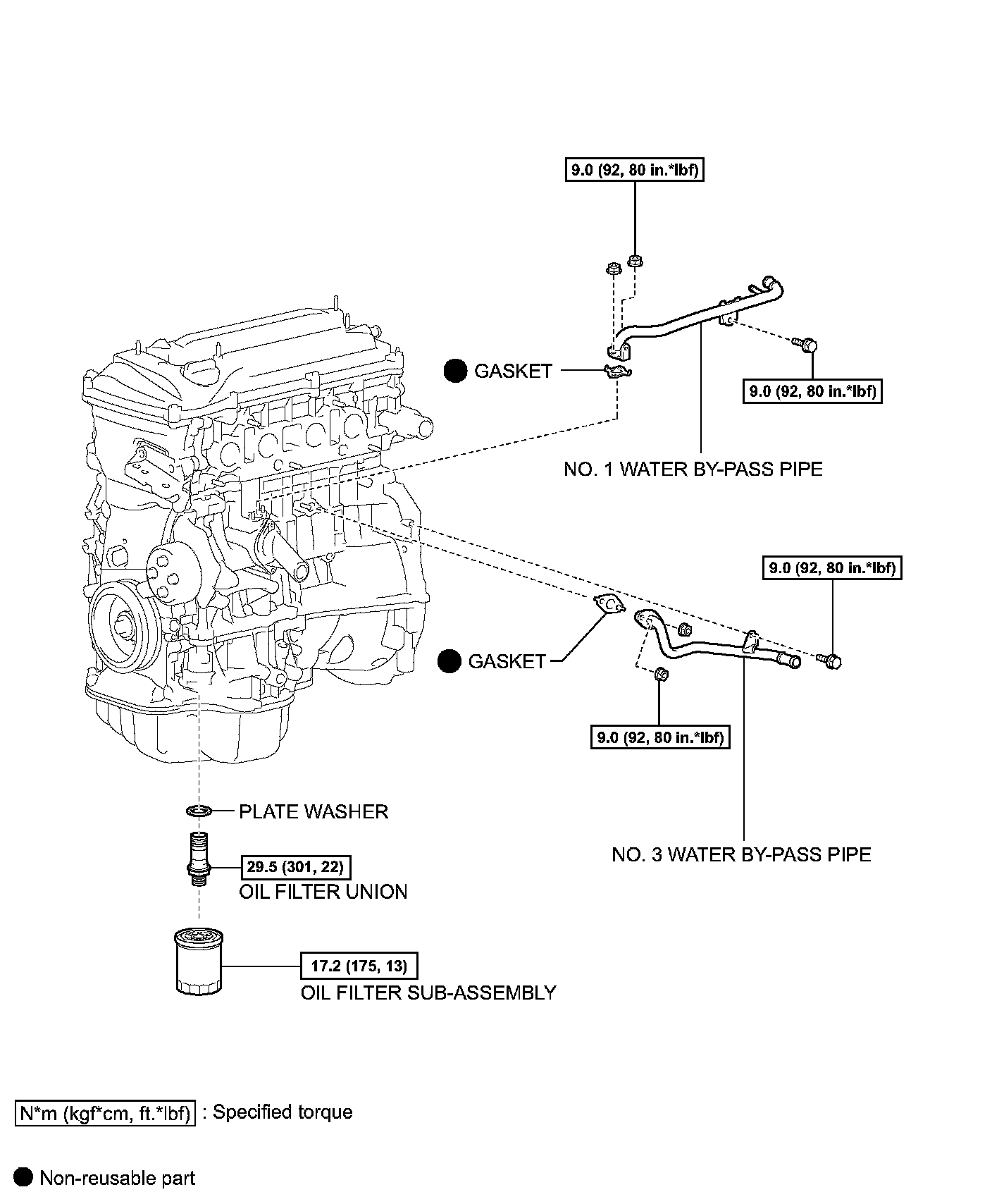
Engine Unit Components:
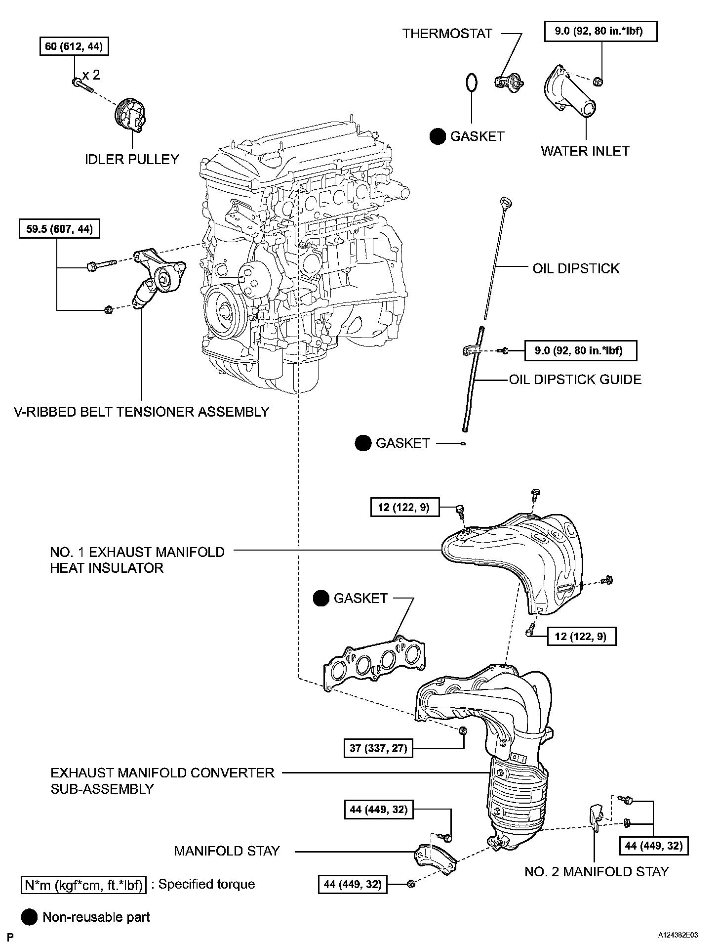
Engine Unit Components:
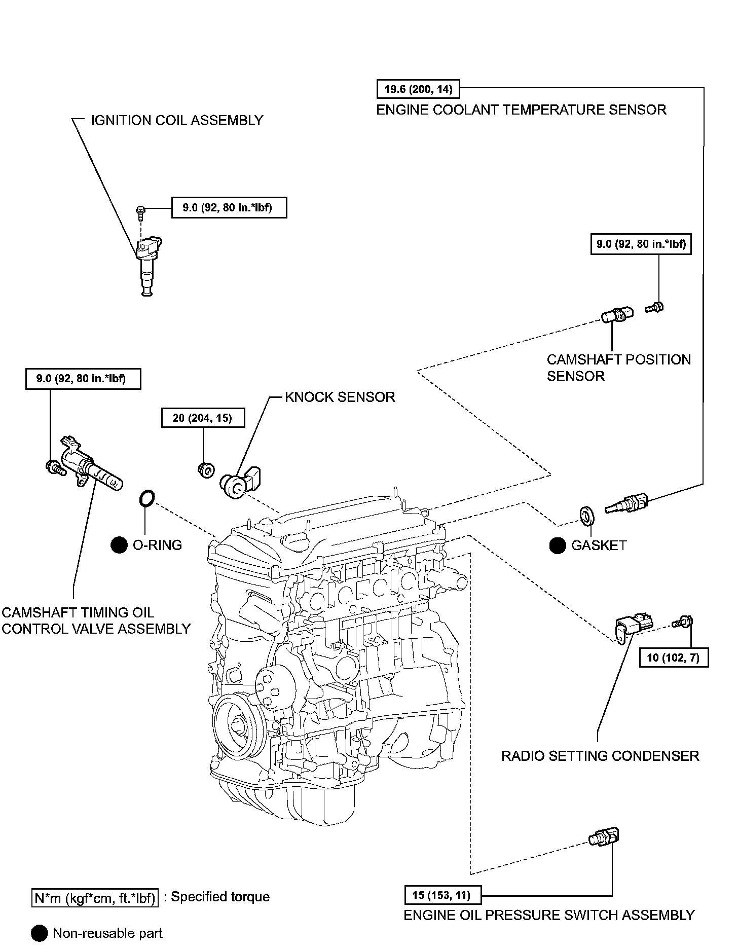
Engine Unit Components:
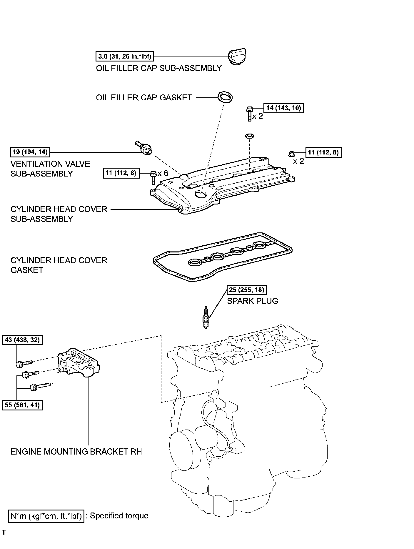
Engine Unit Components:
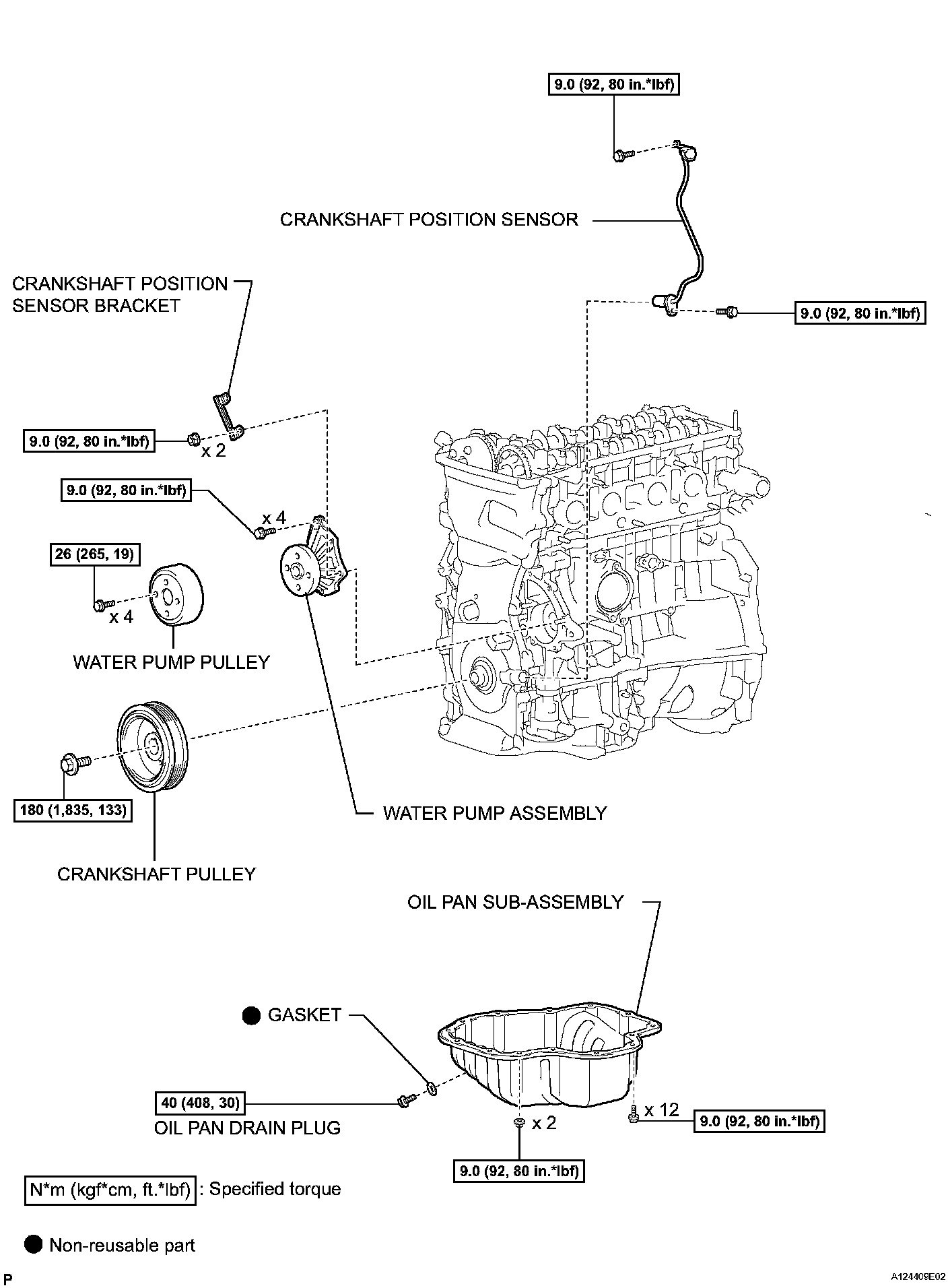
Engine Unit Components:
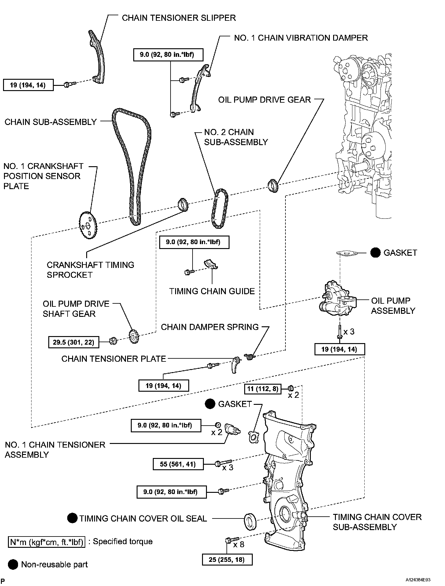
Engine Unit Components:
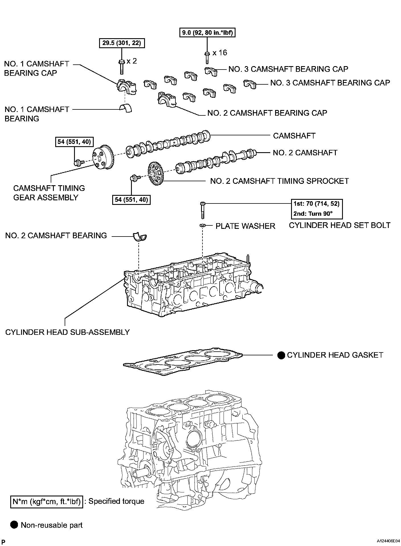
Engine Unit Components:
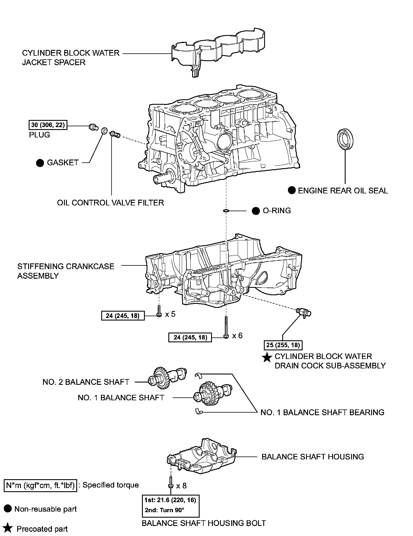
Engine Unit Components:
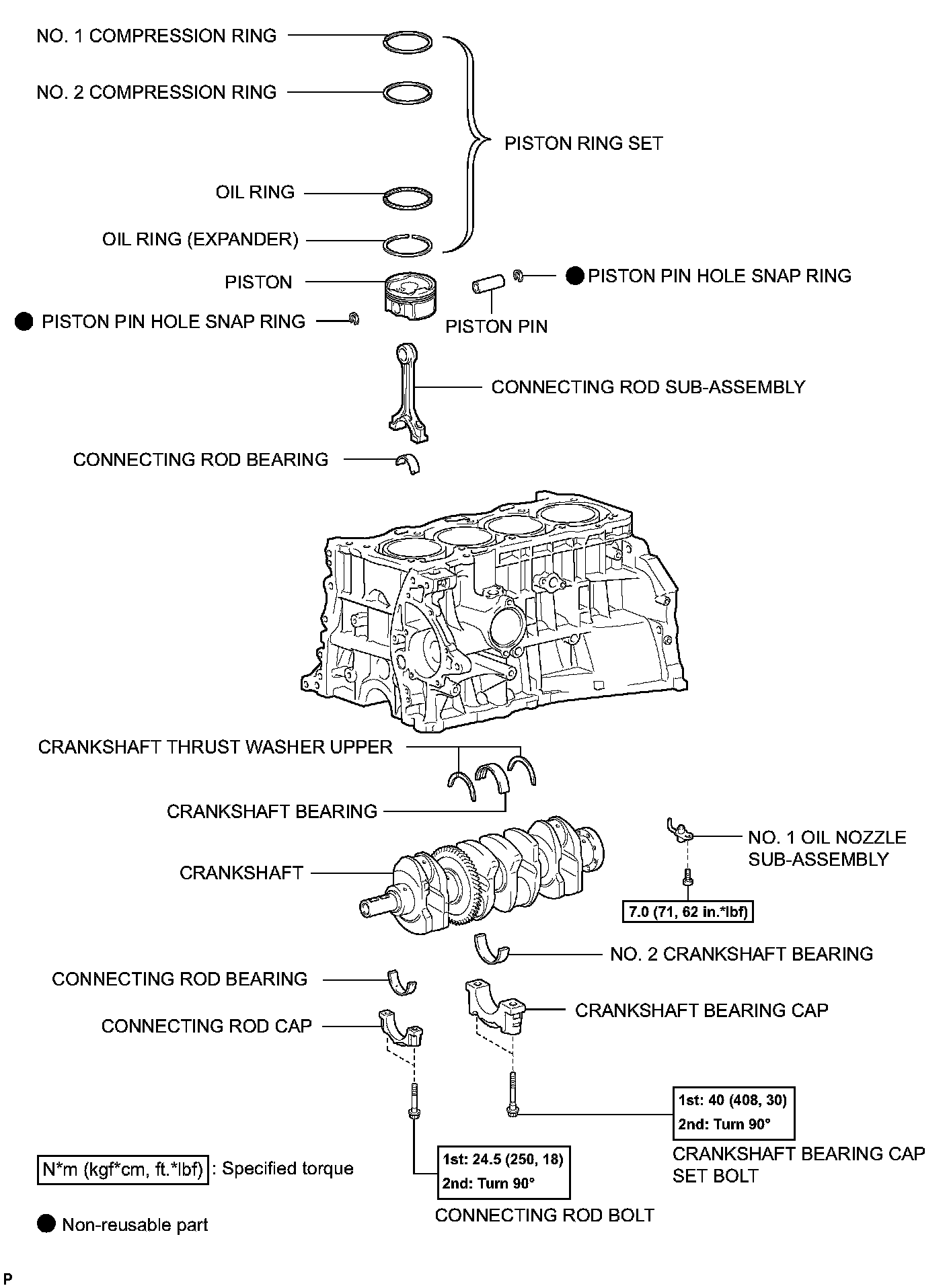
DISASSEMBLY
1. REMOVE IDLER PULLEY
2. REMOVE OIL DIPSTICK
3. REMOVE OIL DIPSTICK GUIDE
4. REMOVE MANIFOLD STAY
5. REMOVE NO. 2 MANIFOLD STAY
6. REMOVE NO. 1 EXHAUST MANIFOLD HEAT INSULATOR
7. REMOVE EXHAUST MANIFOLD CONVERTER SUB-ASSEMBLY
8. REMOVE WATER INLET
9. REMOVE THERMOSTAT
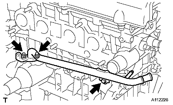
10. REMOVE NO. 1 WATER BY-PASS PIPE
a. Remove the bolt, 2 nuts, pipe and gasket.
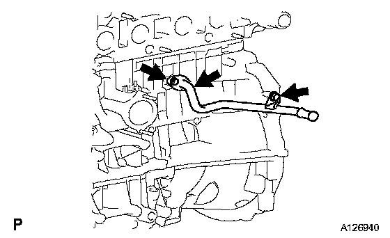
11. REMOVE NO. 3 WATER BY-PASS PIPE
a. Remove the bolt, 2 nuts, pipe and gasket.
12. REMOVE V-RIBBED BELT TENSIONER ASSEMBLY
13. REMOVE CAMSHAFT TIMING OIL CONTROL VALVE ASSEMBLY
14. REMOVE KNOCK SENSOR
15. REMOVE RADIO SETTING CONDENSER
16. REMOVE OIL PRESSURE SWITCH ASSEMBLY
17. REMOVE ENGINE COOLANT TEMPERATURE SENSOR
18. REMOVE CAMSHAFT POSITION SENSOR
19. REMOVE IGNITION COIL ASSEMBLY
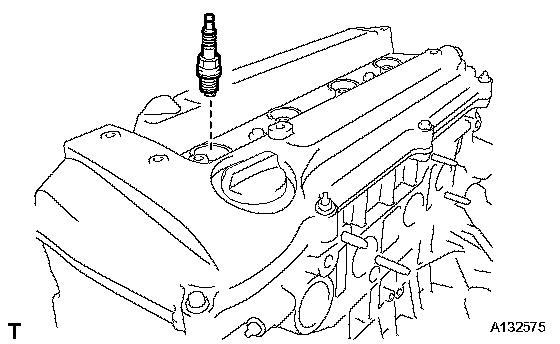
20. REMOVE SPARK PLUG
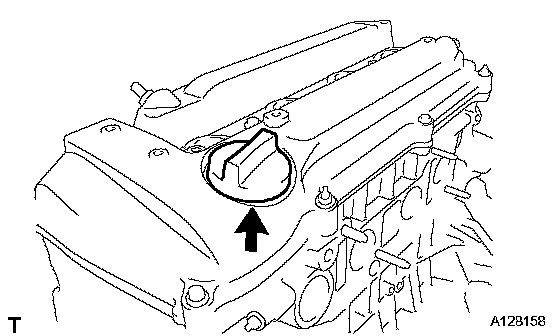
21. REMOVE OIL FILLER CAP SUB-ASSEMBLY
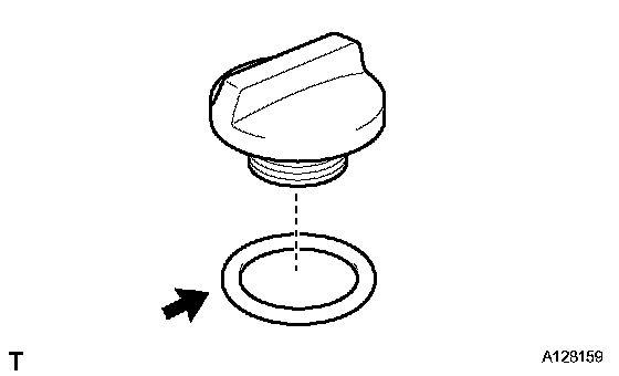
22. REMOVE OIL FILLER CAP GASKET
23. REMOVE VENTILATION VALVE SUB-ASSEMBLY
24. REMOVE CYLINDER HEAD COVER SUB-ASSEMBLY
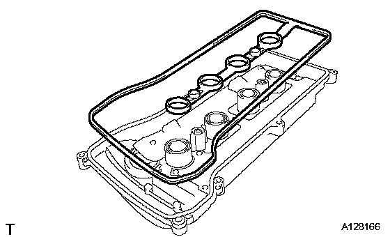
25. REMOVE CYLINDER HEAD COVER GASKET
26. REMOVE OIL FILTER SUB-ASSEMBLY
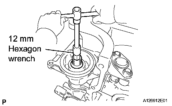
27. REMOVE OIL FILTER UNION
a. Using a 12 mm hexagon wrench, remove the oil filter union.
28. REMOVE CRANKSHAFT POSITION SENSOR
29. REMOVE WATER PUMP PULLEY
30. REMOVE WATER PUMP ASSEMBLY
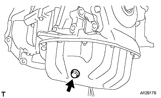
31. REMOVE OIL PAN DRAIN PLUG
32. REMOVE OIL PAN SUB-ASSEMBLY
33. REMOVE CRANKSHAFT PULLEY
34. REMOVE NO. 1 CHAIN TENSIONER ASSEMBLY
35. REMOVE TIMING CHAIN COVER SUB-ASSEMBLY
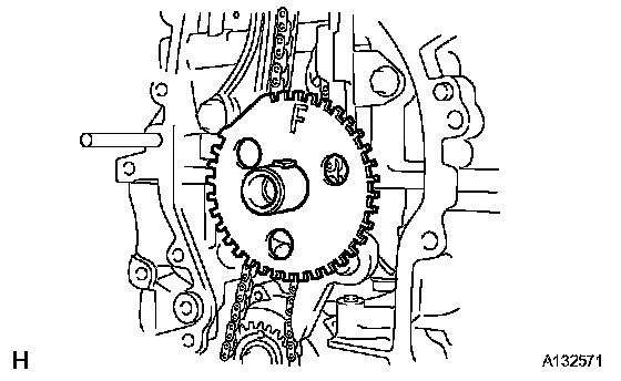
36. REMOVE NO. 1 CRANKSHAFT POSITION SENSOR PLATE
37. REMOVE TIMING CHAIN GUIDE
38. REMOVE CHAIN TENSIONER SLIPPER
39. REMOVE NO. 1 CHAIN VIBRATION DAMPER
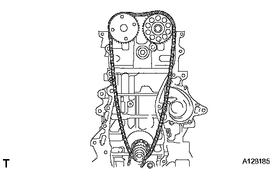
40. REMOVE CHAIN SUB-ASSEMBLY
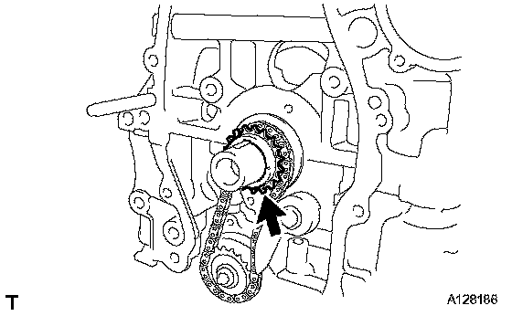
41. REMOVE CRANKSHAFT TIMING SPROCKET
42. REMOVE NO. 2 CHAIN SUB-ASSEMBLY
43. REMOVE OIL PUMP DRIVE GEAR
44. REMOVE OIL PUMP ASSEMBLY
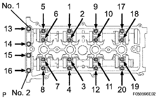
45. REMOVE CAMSHAFT
a. Using several steps, uniformly loosen and remove the 20 bearing cap bolts in the sequence shown in the illustration.
b. Remove the 10 bearing caps, then remove the camshaft and No. 2 camshaft.
46. REMOVE CYLINDER HEAD SUB-ASSEMBLY
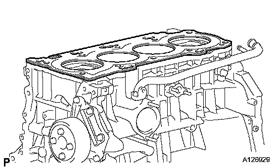
47. REMOVE CYLINDER HEAD GASKET
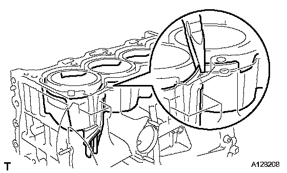
48. REMOVE CYLINDER BLOCK WATER JACKET SPACER
a. Using needle-nose pliers, remove the cylinder block water jacket spacer from the water jacket.
NOTICE: Before turning the cylinder block upside down, make sure that the water jacket spacer is removed, as it will fall out.
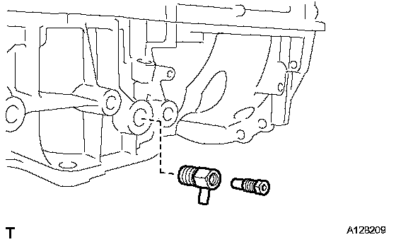
49. REMOVE CYLINDER BLOCK WATER DRAIN COCK SUB-ASSEMBLY
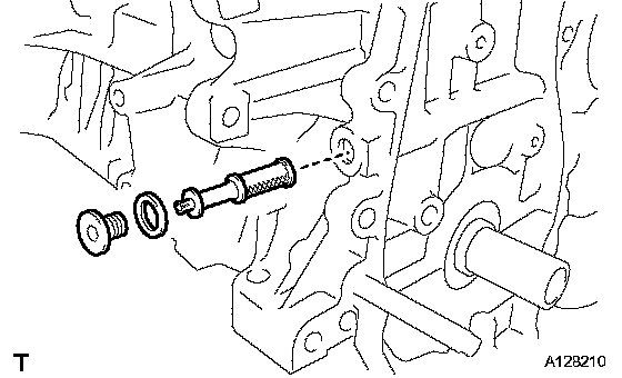
50. REMOVE OIL CONTROL VALVE FILTER
a. Using a 6 mm socket hexagon wrench, remove the plug and gasket.
b. Remove the oil control valve filter.
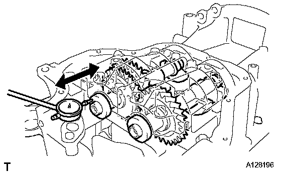
51. INSPECT BALANCE SHAFT THRUST CLEARANCE
a. Using a dial indicator, measure the thrust clearance while moving the balance shaft back and forth.
Standard thrust clearance: 0.05 to 0.09 mm (0.0020 to 0.0035 inch)
Maximum thrust clearance: 0.09 mm (0.0035 inch)
If the thrust clearance is greater than the maximum, replace the balance shaft housing and bearings. If necessary, replace the balance shaft.
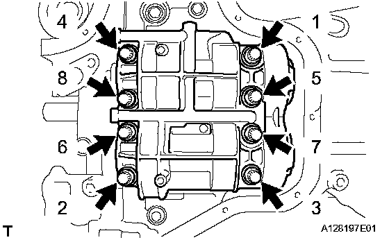
52. INSPECT BALANCE SHAFT OIL CLEARANCE
a. Using several steps, uniformly loosen and remove the 8 bolts in the sequence shown in the illustration.
b. Remove the balance shaft housing from the crankcase.
HINT: Keep the lower bearing and balance shaft housing together.
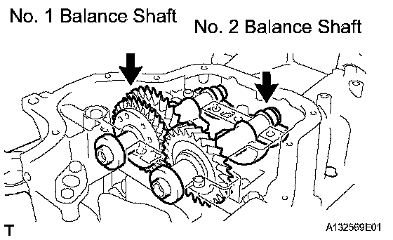
c. Lift out the No. 1 and No. 2 balance shafts.
HINT: Keep the upper bearing with the crankcase.
d. Clean each bearing and journal.
e. Check each bearing and journal for pitting and scratches.
If a bearing or journal is damaged, replace the bearings. If necessary, replace the balance shaft.
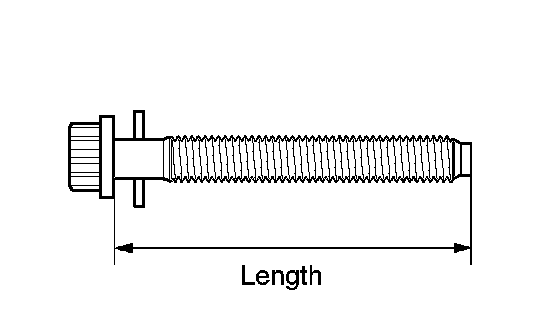
f. Inspect the balance shaft housing bolt.
(1) Using a vernier caliper, measure the length of the bolts from the seat to the end.
Standard bolt length: 58.3 to 59.7 mm (2.295 to 2.350 inch)
Maximum bolt length: 60.3 mm (2.374 inch)
If the bolt length is greater than the maximum, replace the balance shaft bolt.
g. Place the No. 1 and No. 2 balance shafts onto the crankcase.
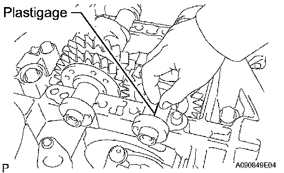
h. Lay a strip of Plastigage across each journal.
i. Install the balance shaft housing.
j. Apply a light coat of engine oil on the threads and under the heads of the bolts.
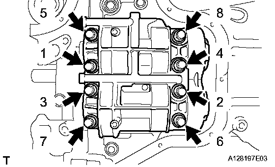
k. Using several steps, uniformly install and tighten the 8 bolts in the sequence shown in the illustration.
Torque: 21.6 Nm (220 kgf-cm, 16 ft. lbs.)
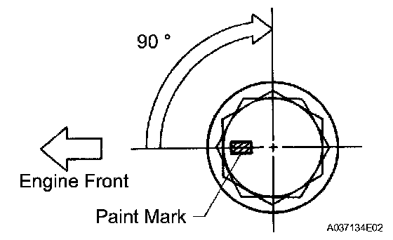
l. Mark the front of the bolts with paint.
m. Retighten the bolts 90° as shown in the illustration.
n. Check that the paint mark is now at a 90° angle to the front.
o. Remove the balance shaft housing from the crankcase.
p. Measure the Plastigage at its widest point.
Standard oil clearance: 0.004 to 0.049 mm (0.0002 to 0.0019 inch)
Maximum oil clearance: 0.049 mm (0.0019 inch)
NOTICE: Remove the Plastigage completely after the measurement. If the oil clearance is greater than the maximum, replace the bearing. If necessary, replace the balance shaft.
HINT: If replacing a bearing, select a new one with the same number.
Standard Balance Shaft Housing Journal Bore Diameter:
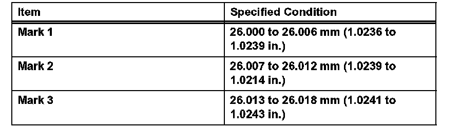
Standard balance shaft journal diameter: 22.985 to 23.000 mm (0.9049 to 0.9055 inch)
Standard Bearing Center Wall Thickness:
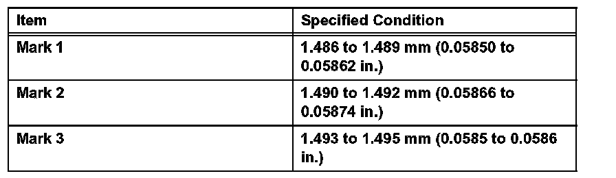
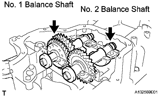
53. REMOVE BALANCE SHAFT
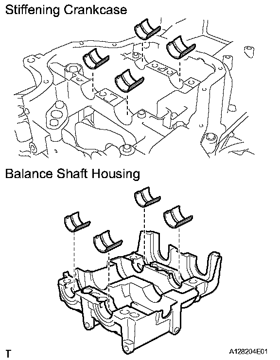
54. REMOVE NO. 1 BALANCE SHAFT BEARING
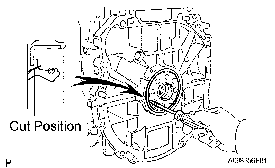
55. REMOVE ENGINE REAR OIL SEAL
a. Using a knife, cut off the lip of the oil seal.
b. Using a screwdriver with its tip wrapped with tape, pry out the oil seal.
NOTICE: After removing, check the crankshaft for damage. If damaged, smooth the surface with 400-grit sandpaper.
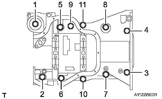
56. REMOVE STIFFENING CRANKCASE ASSEMBLY
a. Using several steps, uniformly loosen and remove the 11 bolts in the sequence shown in the illustration.
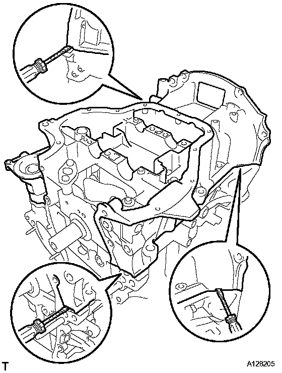
b. Remove the crankcase by prying the portions between the crankcase and cylinder block.
NOTICE: Be careful not to damage the contact surfaces of the crankcase and cylinder block.
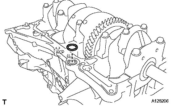
c. Remove the O-ring from the cylinder block.
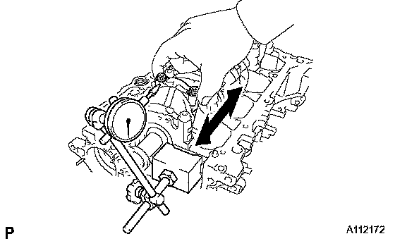
57. INSPECT CONNECTING ROD THRUST CLEARANCE
a. Using a dial indicator, measure the thrust clearance while moving the connecting rod back and forth.
Standard thrust clearance: 0.160 to 0.362 mm (0.0063 to 0.0143 inch)
Maximum thrust clearance: 0.362 mm (0.0143 inch)
If the thrust clearance is greater than the maximum, replace the connecting rod. If necessary, replace the crankshaft.