Part 2
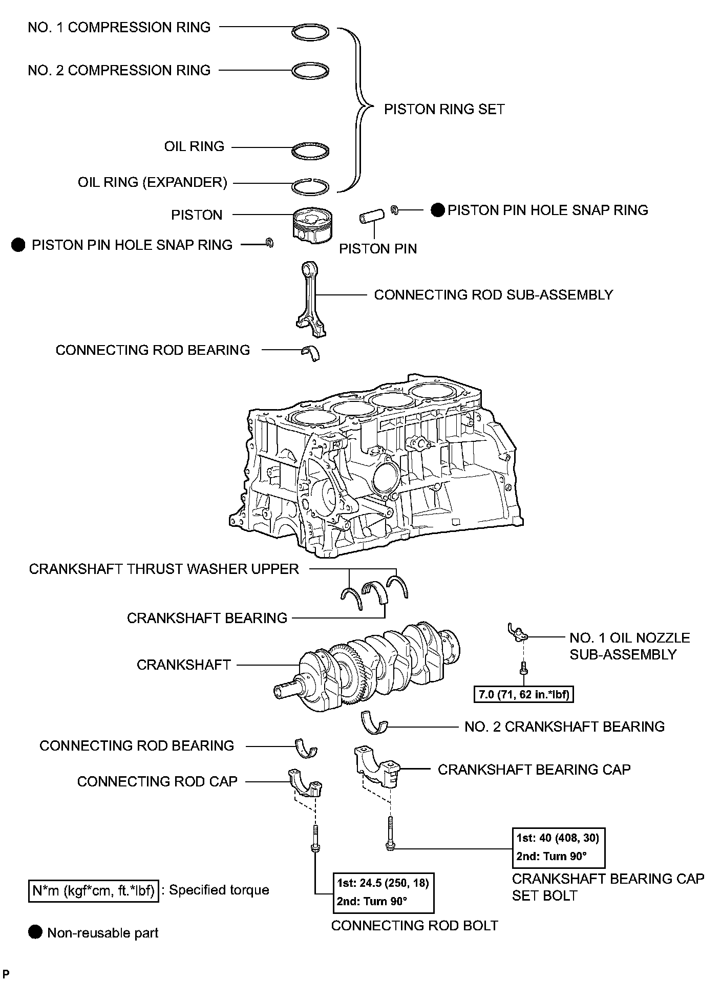
ENGINE UNITEngine Unit Components:
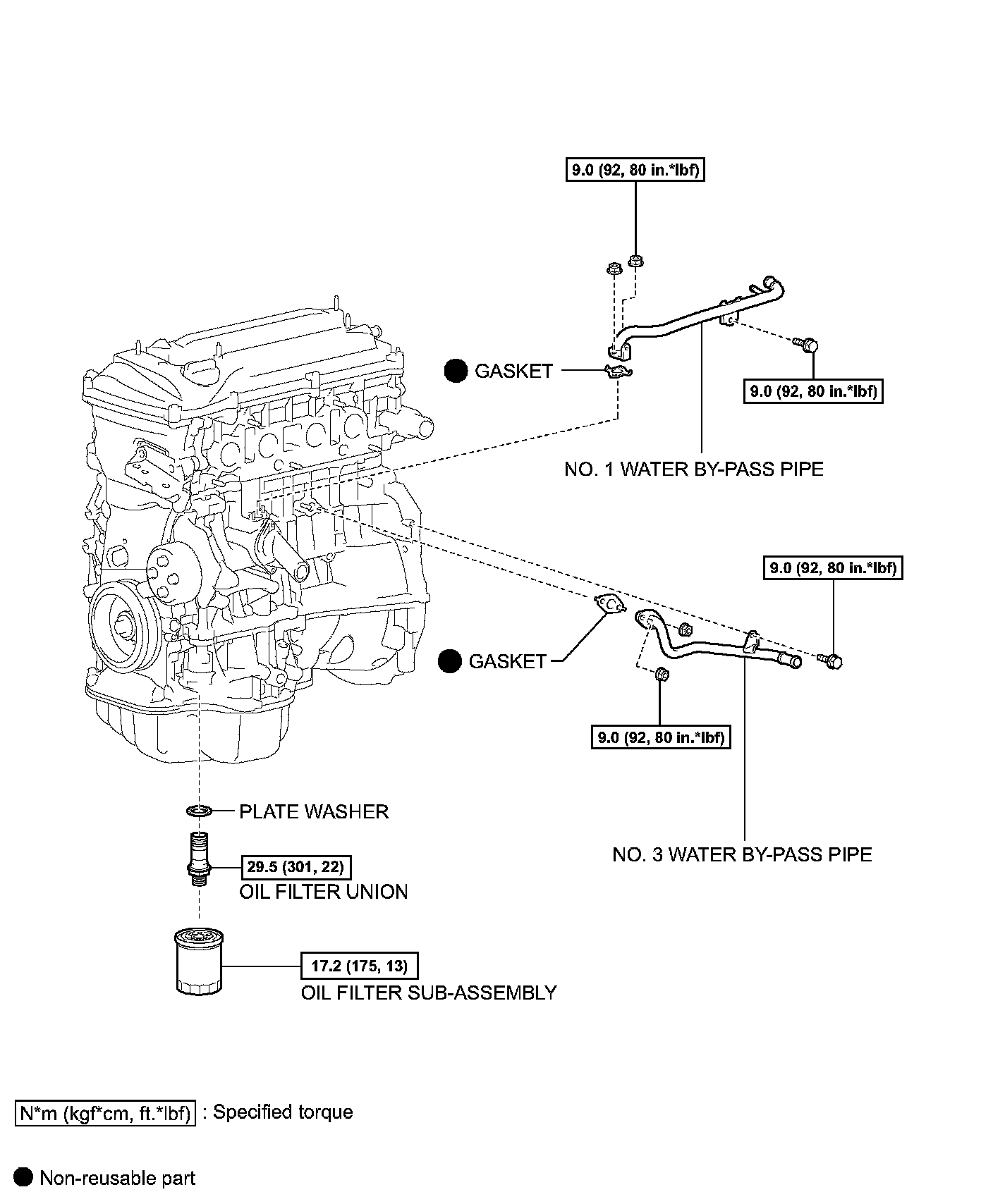
Engine Unit Components:
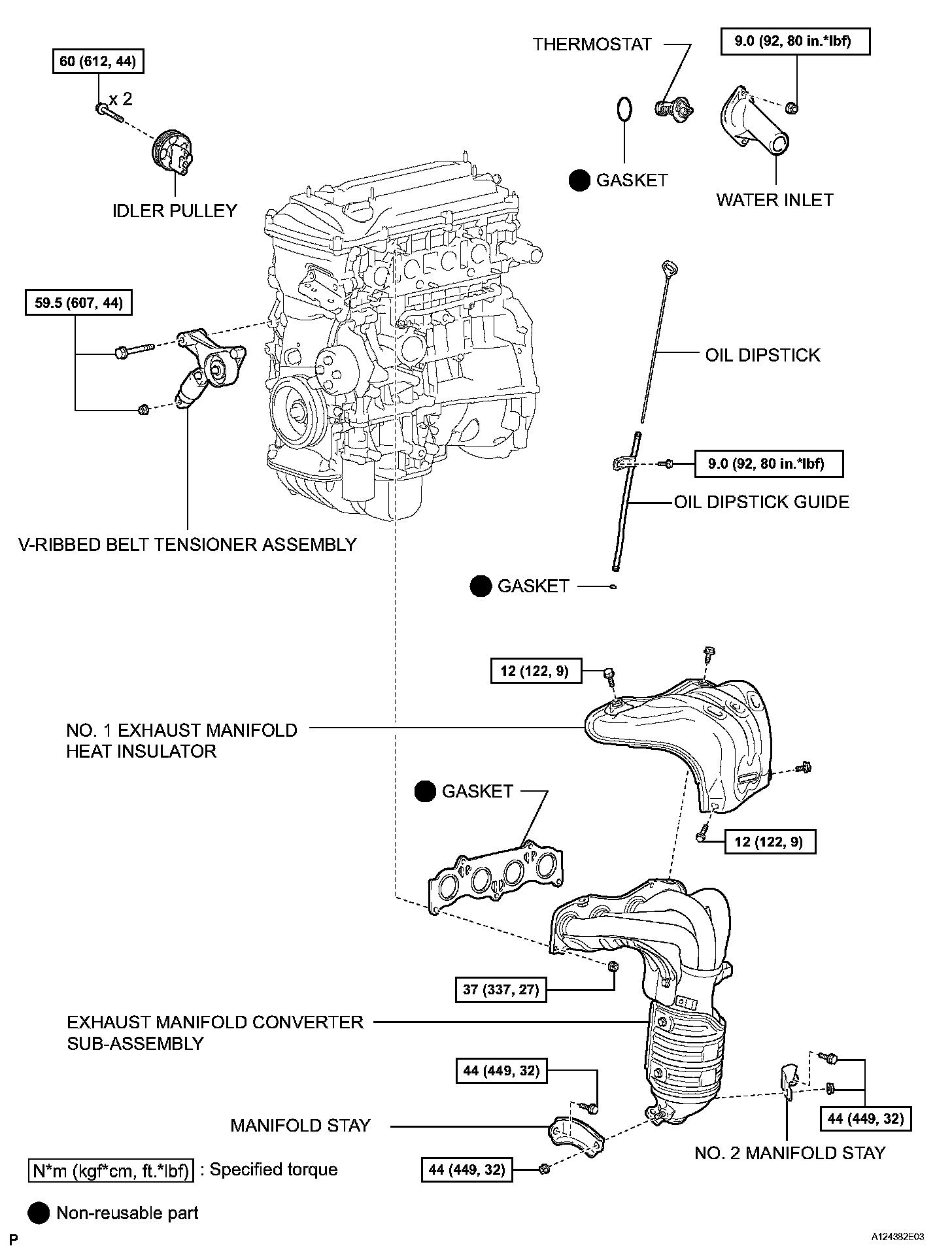
Engine Unit Components:
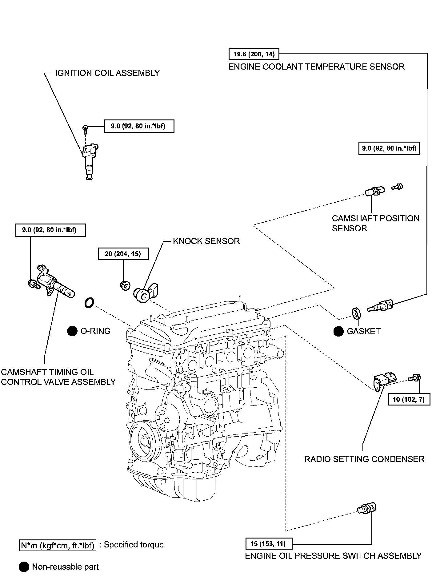
Engine Unit Components:
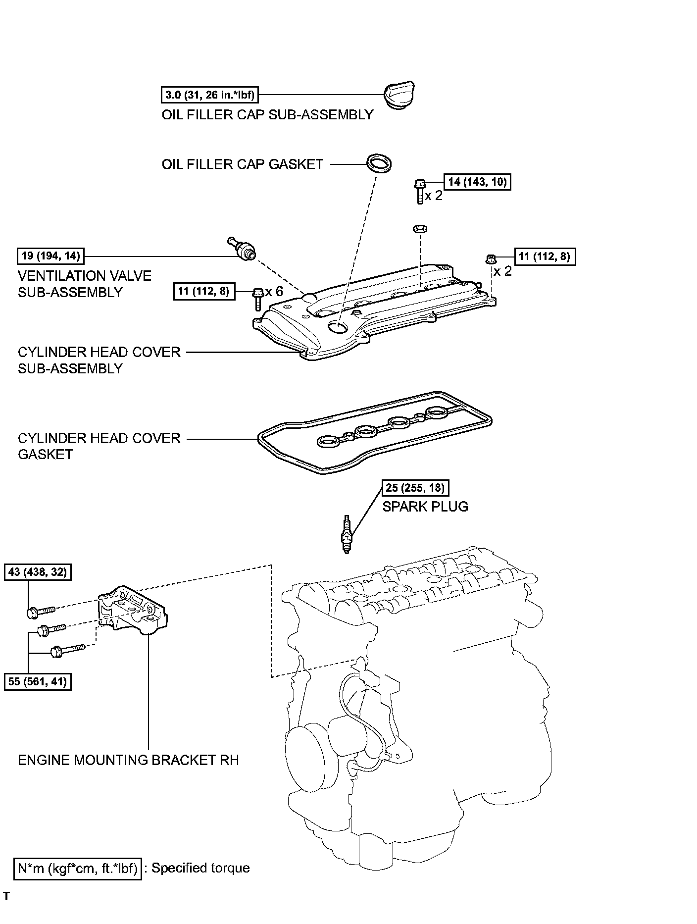
Engine Unit Components:
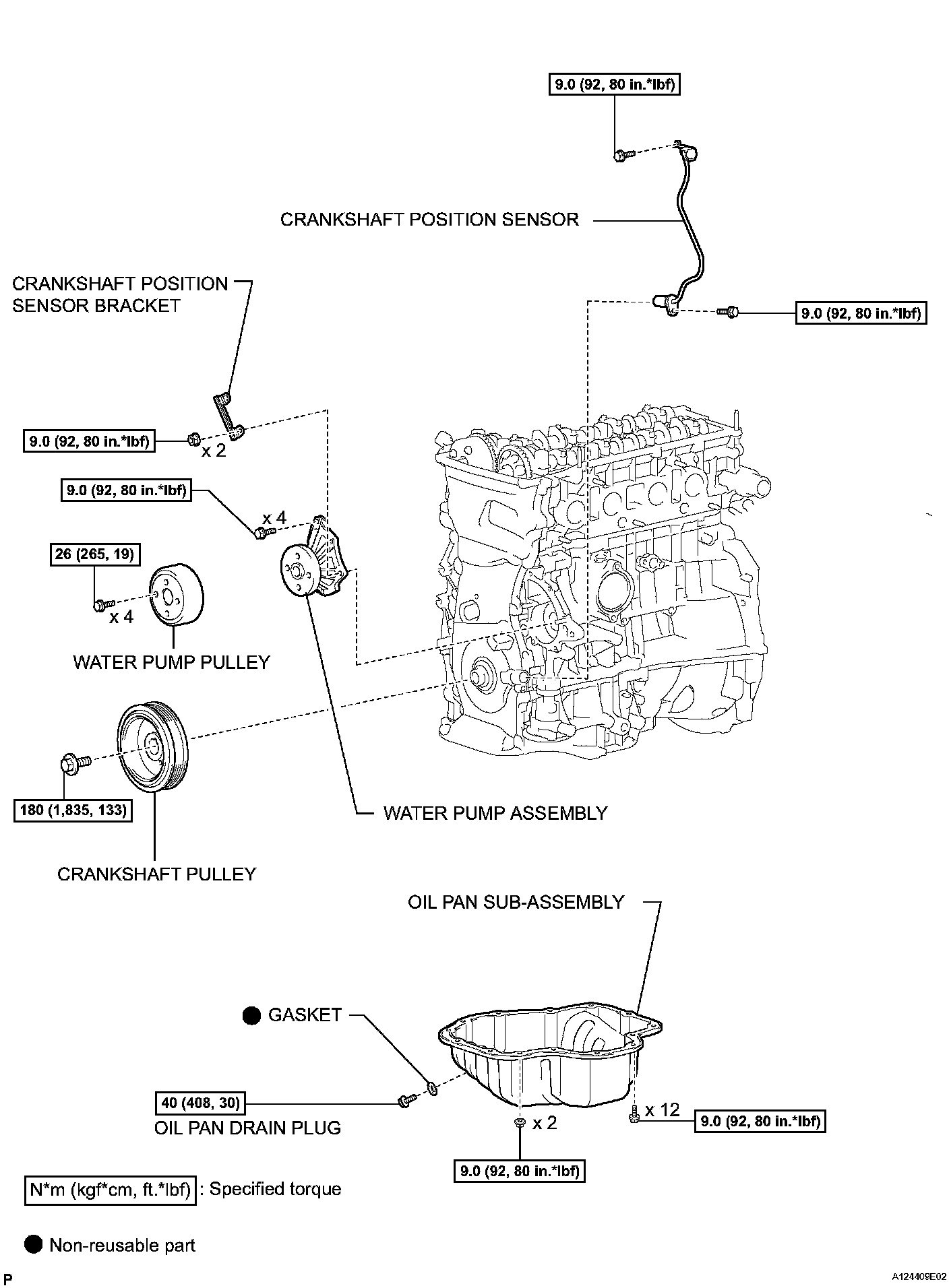
Engine Unit Components:
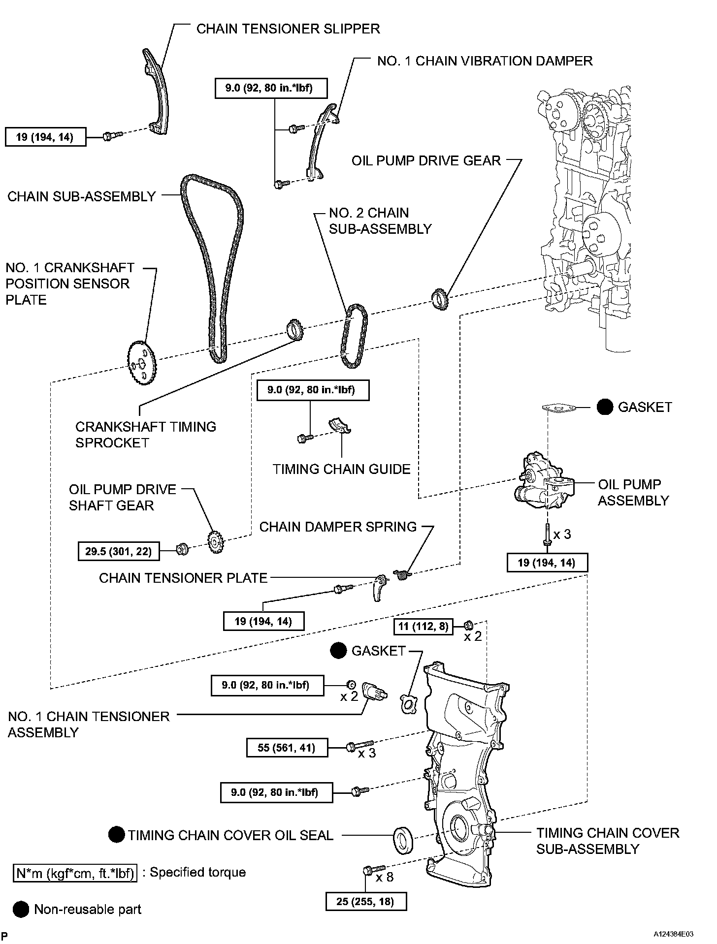
Engine Unit Components:
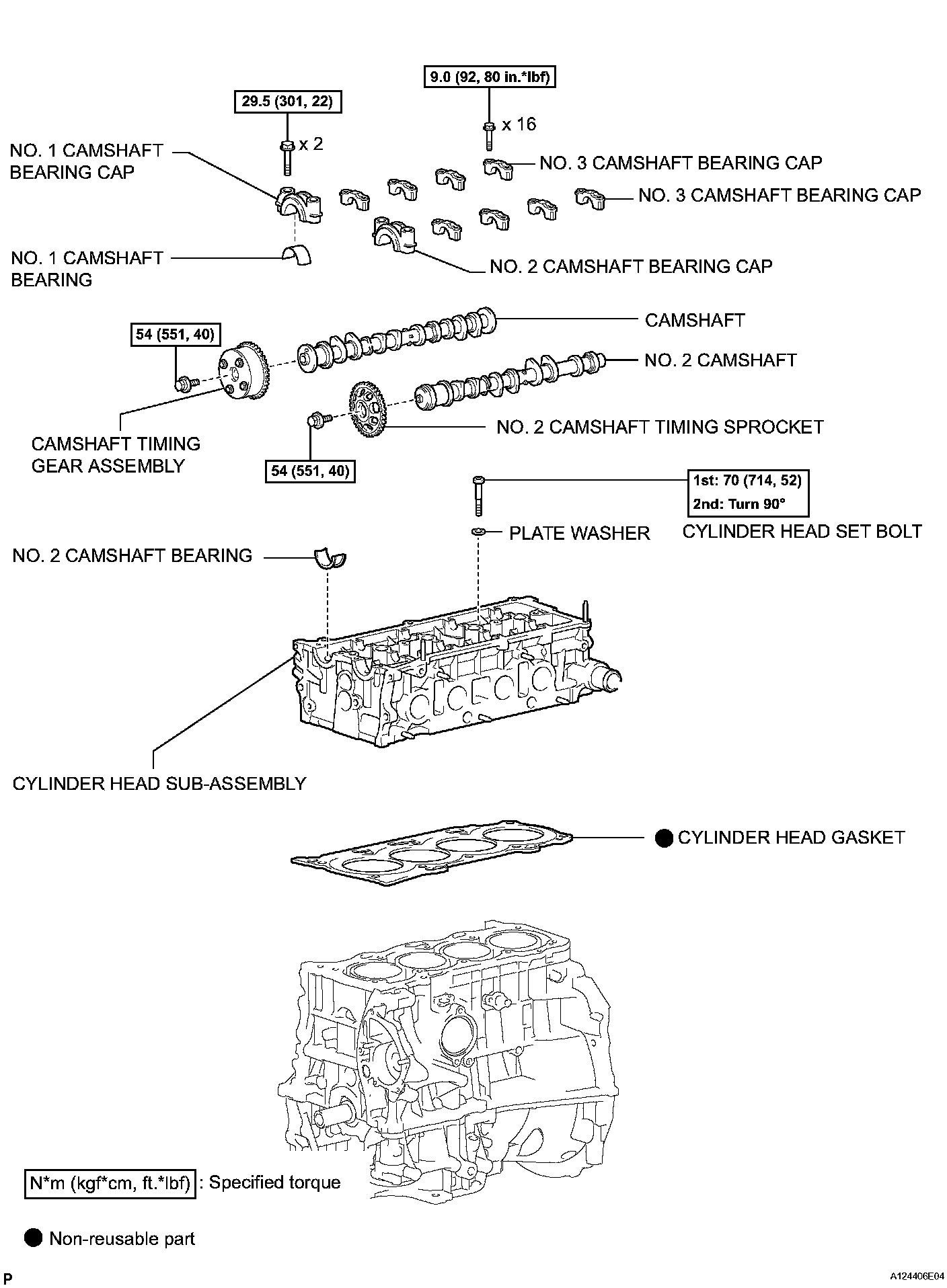
Engine Unit Components:
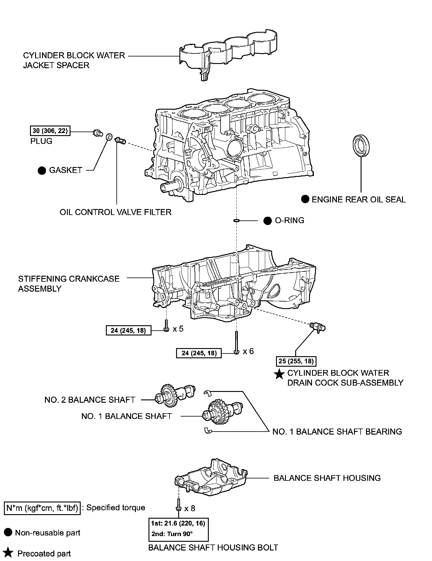
Engine Unit Components:
DISASSEMBLY (continued)
58. INSPECT CONNECTING ROD OIL CLEARANCE
NOTICE: Do not turn the crankshaft during the measurement.
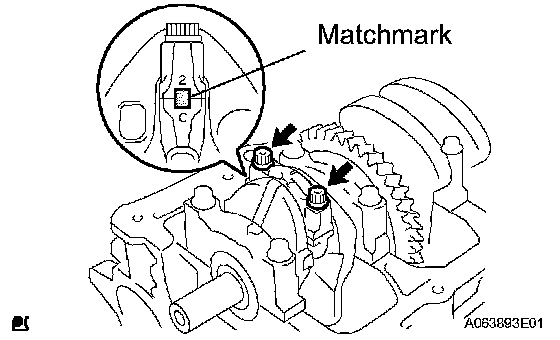
a. Using marking paint, write the matched cylinder number on each connecting rod and cap.
HINT: The matchmarks in the connecting rods and caps are for ensuring correct reassembly.
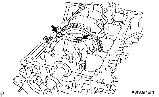
b. Using a 12 mm socket wrench, remove the 2 bolts and connecting rod cap.
c. Clean the crank pin and bearing.
d. Check the crank pin and bearing for pitting and scratches.
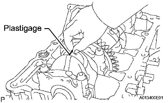
e. Lay a strip of Plastigage on the crank pin.
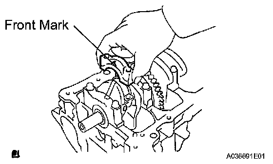
f. Check that the front mark of the connecting rod cap is facing in the correct direction.
g. Apply a light coat of engine oil to the threads and under the heads of the connecting rod bolts.
h. Using a 12 mm socket wrench, tighten the bolts in several passes to the specified torque.
Torque: 24.5 Nm (250 kgf-cm, 18 ft. lbs.)
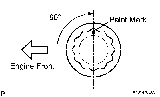
i. Mark the front of the connecting rod bolts with paint.
j. Retighten the cap bolts 90° as shown in the illustration.
k. Check that the crankshaft turns smoothly
l. Using a 12 mm socket wrench, remove the 2 bolts and connecting rod cap.
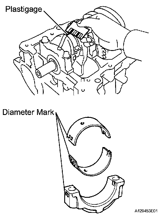
m. Measure the Plastigage at its widest point.
Standard oil clearance: 0.024 to 0.048 mm (0.0009 to 0.0019 inch)
Maximum oil clearance: 0.08 mm (0.0032 inch)
NOTICE: Remove the Plastigage completely after the measurement. If the oil clearance is greater than the maximum, replace the connecting rod bearing. If necessary, grind or replace the crankshaft.
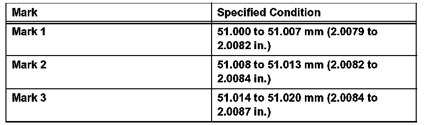
HINT: If replacing a bearing, select a new one with the same number as marked on the connecting rod. There are 3 sizes of standard bearings, marked "1" "2" and "3" accordingly.
Standard Connecting Rod Large End Bore Diameter:
Standard Connecting Rod Bearing Thickness:
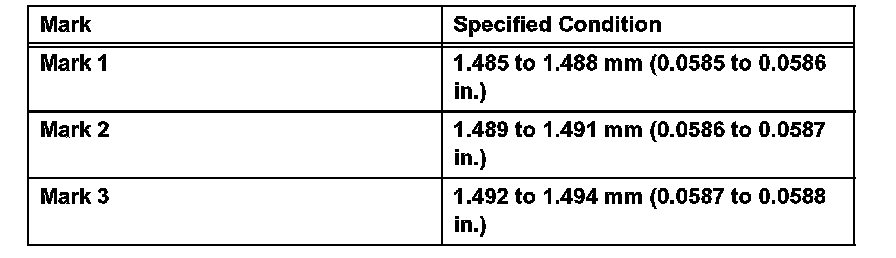
Standard crankshaft pin diameter: 47.990 to 48.000 (1.8894 to 1.8898 inch)
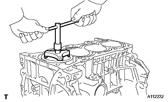
59. REMOVE PISTON WITH CONNECTING ROD
a. Using a ridge reamer, remove all the carbon from the top of the cylinder.
b. Push the piston, connecting rod assembly and upper bearing through the top of the cylinder block.
HINT:
^ Keep the bearing, connecting rod and cap together.
^ Arrange the piston and connecting rod assemblies in the correct order.
60. REMOVE CONNECTING ROD BEARING
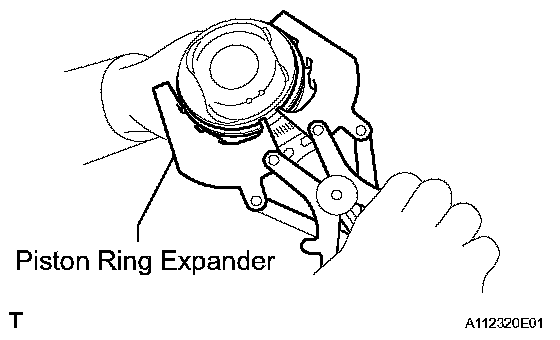
61. REMOVE PISTON RING SET
a. Using a piston ring expander, remove the 2 compression rings.
b. Remove the oil ring and expander by hand.
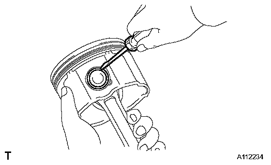
62. REMOVE PISTON PIN HOLE SNAP RING
a. Using a small screwdriver, pry out the 2 snap rings.
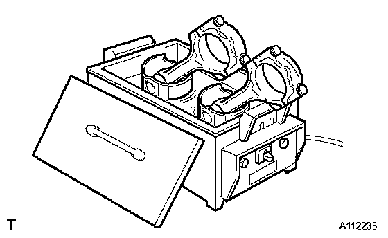
63. REMOVE PISTON
a. Gradually heat the piston up to 80 to 90°C (176 to 194°F).
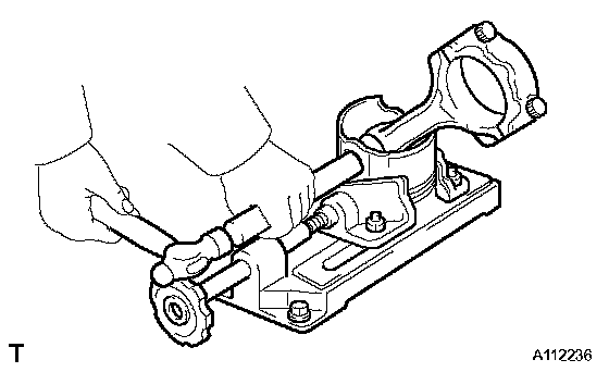
b. Using a plastic-faced hammer and brass bar, lightly tap out the piston pin, then remove the connecting rod.
HINT:
^ The piston and pin are a matched set.
^ Arrange the piston, pin, ring, connecting rod and bearings in the correct order.
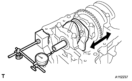
64. INSPECT CRANKSHAFT THRUST CLEARANCE
a. Using a dial indicator, measure the thrust clearance while prying the crankshaft back and forth with a screwdriver.
Standard thrust clearance: 0.04 to 0.24 mm (0.0016 to 0.0095 inch)
Maximum thrust clearance: 0.30 mm (0.012 inch)
If the thrust clearance is greater than the maximum, replace the thrust washers as a set.
HINT: The thrust washer thickness is 1.93 to 1.98 mm (0.0760 to 0.0780 inch).
65. INSPECT CRANKSHAFT OIL CLEARANCE
NOTICE: Do not turn the crankshaft during the measurement.
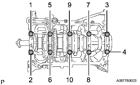
a. Using several steps, uniformly loosen and remove the 10 bearing cap bolts in the sequence shown in the illustration.
b. Remove the 5 bearing caps from the cylinder block.
HINT:
^ Keep the No. 2 crankshaft bearings and crankshaft bearing caps together.
^ Arrange the bearing caps in correct order.
c. Remove the crankshaft.
HINT: Keep the crankshaft bearings and crankshaft thrust washer uppers together with the cylinder block.
d. Clean each main journal and bearing.
e. Check each main journal and bearing for pitting and scratches.
^ If the journal or bearing is damaged, replace the bearings.
^ If necessary, replace the crankshaft.
f. Place the crankshaft onto the cylinder block.
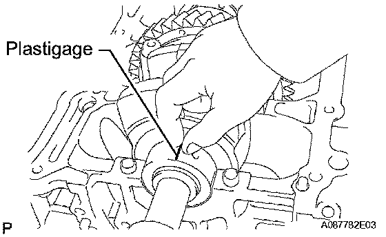
g. Lay a strip of Plastigage across each journal.
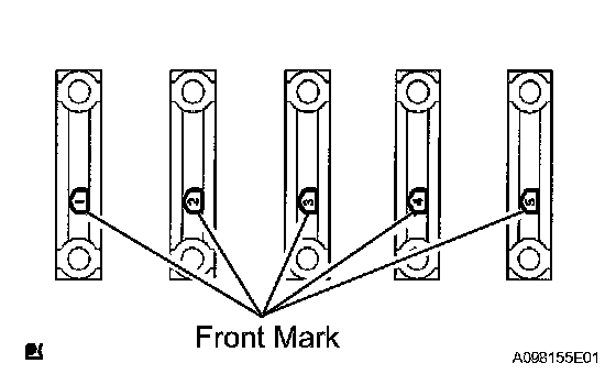
h. Examine the front marks and numbers, and install the bearing caps onto the cylinder block in the order shown in the illustration.
i. Apply a light coat of engine oil to the threads and under the heads of the crankshaft bearing cap set bolts.
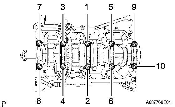
j. Using several steps, uniformly install and tighten the 10 bearing cap bolts in the sequence shown in the illustration.
Torque: 40 Nm (408 kgf-cm, 30 ft. lbs.)
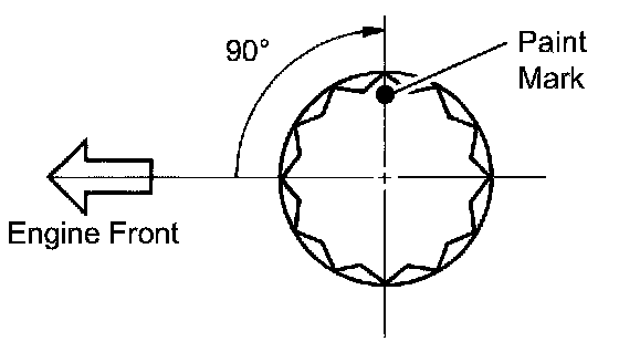
k. Mark the front of the bearing cap bolts with paint.
l. Retighten the 10 bearing cap bolts by 90°.
m. Check that the paint marks are at a 90° angle to the front.
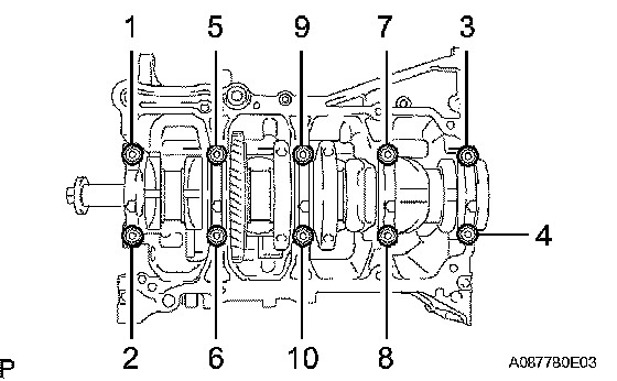
n. Remove the crankshaft bearing caps.
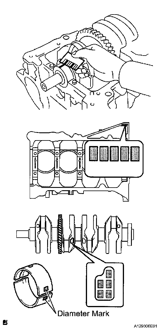
o. Measure the Plastigage at its widest point.
Standard oil clearance: 0.008 to 0.024 mm (0.0003 to 0.0010 inch)
Maximum oil clearance: 0.050 mm (0.0020 inch)
NOTICE: Remove the Plastigage completely after the measurement. If the oil clearance is greater than the maximum, replace the crankshaft bearing. If necessary, replace the crankshaft.

HINT: If replacing a bearing, select a new one with the same number. If the number of the bearing cannot be determined, calculate the correct bearing number by adding together the numbers imprinted on the cylinder block and crankshaft. Then select a new bearing with the calculated number. There are 4 sizes of standard bearings, marked "'1", "2", "3" and "4" accordingly.
EXAMPLE
^ Imprinted number on the cylinder block is 3.
^ Imprinted number on the crankshaft is 4. 3 + 4 = 7
Select the bearing marked "3".
Standard Cylinder Block Journal Bore Diameter:

Standard Crankshaft Journal Diameter (Part 1):

Standard Crankshaft Journal Diameter (Part 2):

Standard Bearing Center Wall Thickness:

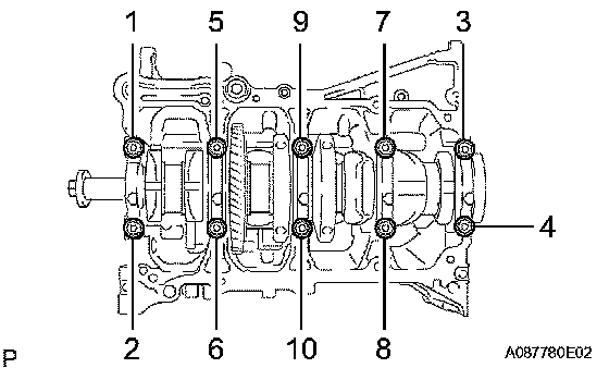
66. REMOVE CRANKSHAFT
a. Using several steps, uniformly loosen and remove the 10 bearing cap bolts in the sequence shown in the illustration.
b. Remove the 5 bearing caps from the cylinder block.
c. Remove the crankshaft from the cylinder block.
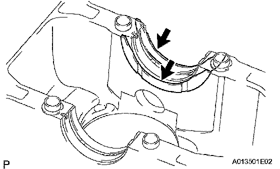
67. REMOVE CRANKSHAFT THRUST WASHER UPPER
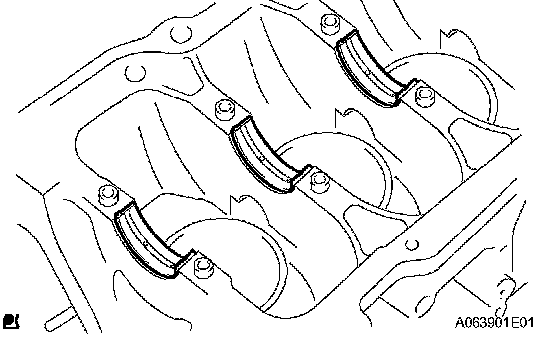
68. REMOVE CRANKSHAFT BEARING
HINT: Arrange the bearings in the correct order.
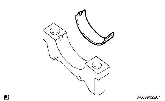
69. REMOVE NO. 2 CRANKSHAFT BEARING
HINT: Arrange the bearings in the correct order.
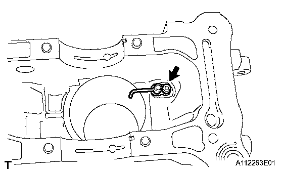
70. REMOVE NO. 1 OIL NOZZLE SUB-ASSEMBLY
a. Remove the 4 bolts and 4 oil nozzles.
REPLACEMENT
1. REPLACE TIMING CHAIN COVER OIL SEAL
HINT: There are 2 methods to replace the oil seal.
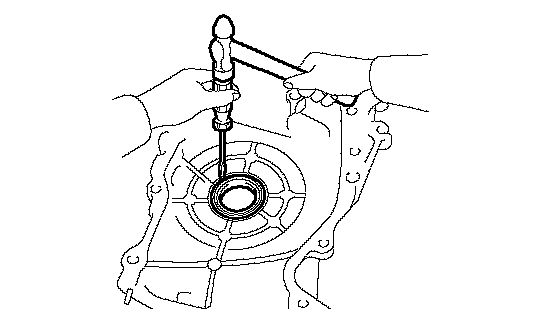
a. If the timing chain cover is removed from the cylinder block:
(1) Using a screwdriver and hammer, tap out the oil seal.
(2) Apply multi-purpose grease to the lip of a new oil seal.
NOTICE: Keep the lip free of foreign objects.
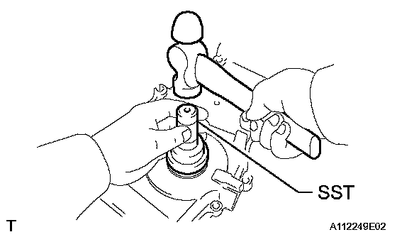
(3) Using SST and a hammer, tap in the new oil seal until its surface is flush with the timing chain cover edge.
SST 09223-22010
NOTICE: Do not tap the oil seal at an angle.
b. If the timing chain cover oil seal is installed to the cylinder block:
(1) Remove the fan and generator V belt.
(2) Remove the crankshaft pulley.
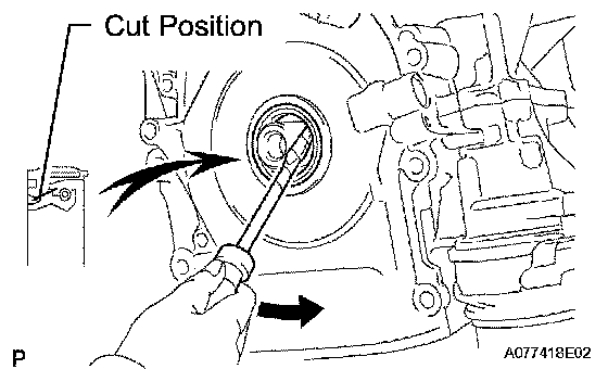
(3) Using a knife, cut off the lip of the oil seal.
(4) Using a screwdriver with its tip wrapped with tape, pry out the oil seal.
NOTICE: After removing, check the crankshaft for damage. If damaged, smooth the surface with 400-grit sandpaper.
(5) Apply multi-purpose grease to the lip of a new oil seal.
NOTICE: Keep the lip free of foreign objects.
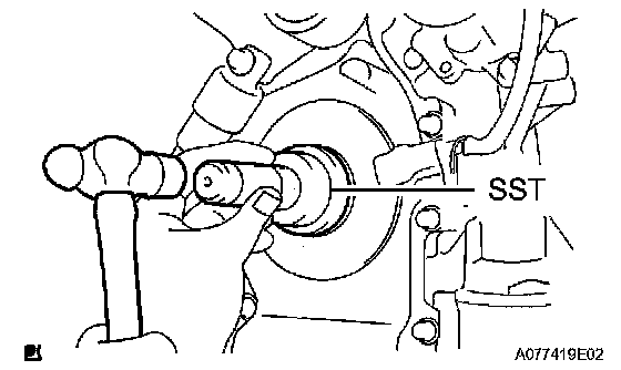
(6) Using SST and a hammer, tap in the new oil seal until its surface is flush with the timing chain cover edge.
SST 09223-22010
NOTICE: Do not tap the oil seal at an angle.
(7) Install the crankshaft pulley.
(8) Install the fan and generator V belt.
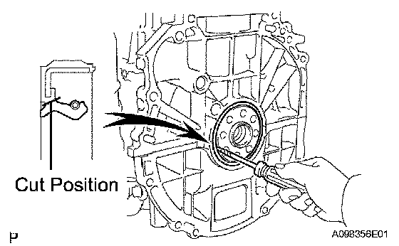
2. REPLACE ENGINE REAR OIL SEAL
a. Using a knife, cut off the lip of the oil seal.
b. Using a screwdriver with its tip wrapped with tape, pry out the oil seal.
NOTICE: After removing, check the crankshaft for damage. If damaged, smooth the surface with 400-grit sandpaper.
c. Apply multi-purpose grease to the lip of a new oil seal.
NOTICE: Keep the lip free of foreign objects.
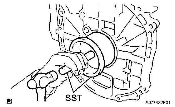
d. Using SST and a hammer, tap in the new oil seal until its surface is flush with the rear oil seal retainer edge.
SST 09223-15030, 09950-70010 (09951-07100)
NOTICE:
^ Wipe any extra grease off the crankshaft.
^ Do not tap the oil seal at an angle.
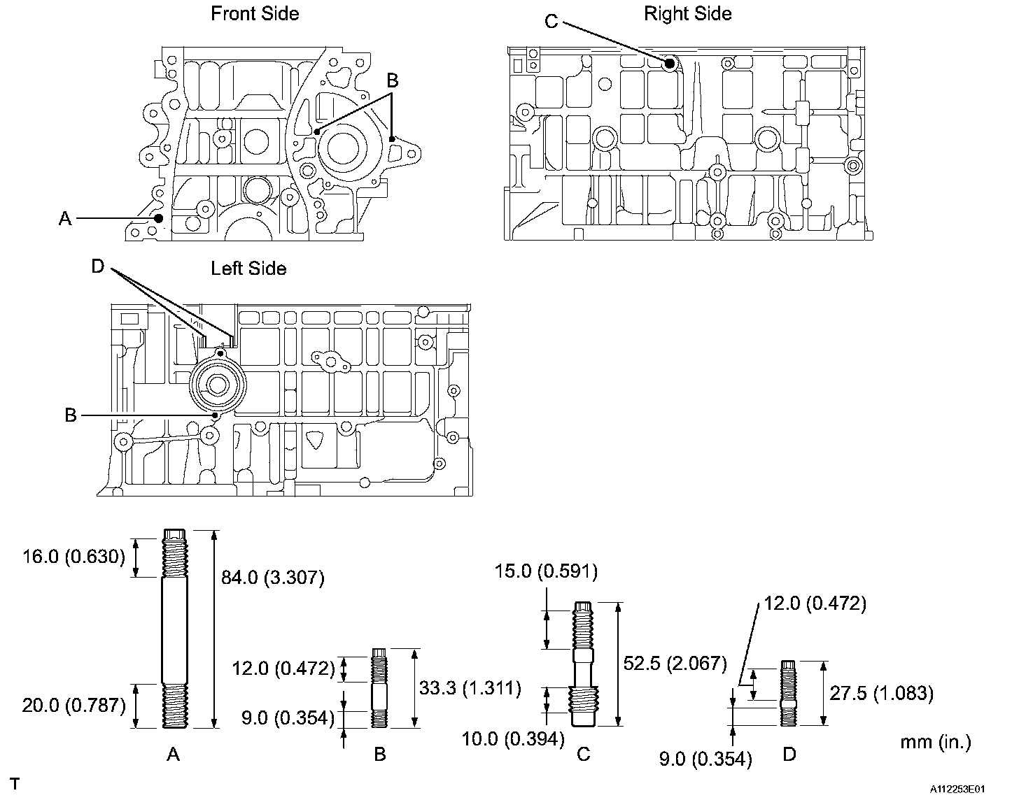
3. REPLACE STUD BOLT (for Cylinder Block)
NOTICE: If the stud bolt is deformed or the threads are damaged, replace it.
a. Remove the 8 stud bolts.
Torque:
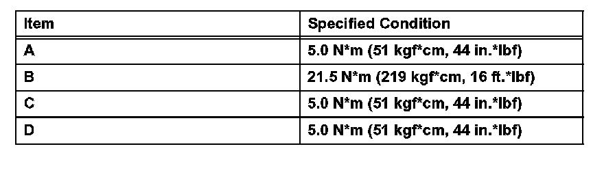
b. Install the 8 stud bolts into the cylinder block.
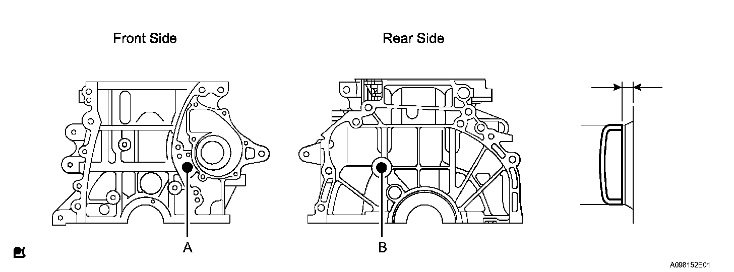
4. REPLACE TIGHT PLUG (for Cylinder Block)
NOTICE: If water leaks from the tight plug or the plug corrodes, replace it.
a. Remove the 2 tight plugs from the engine front and rear side.
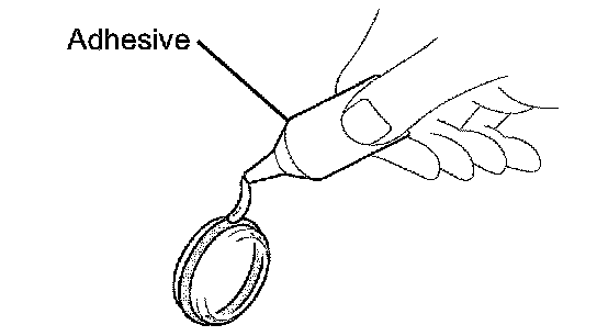
b. Apply adhesive around new tight plugs.
Adhesive: Toyota Genuine Adhesive 1342, Three Bond 1342 or Equivalent
Standard Depth:

c. Using SST, install the 2 tight plugs.
SST 09950-60010 (09951-00200), 09950-70010 (09951-07100)
5. REPLACE RING PIN (for Cylinder Block)
NOTICE: It is not necessary to remove with head pin unless it is being replaced.
a. Remove the 12 ring pins.
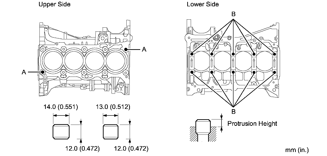
Standard Protrusion Height:

b. Using a plastic-faced hammer, install 12 new ring pins.
6. REPLACE STRAIGHT PIN (for Cylinder Block)
NOTICE: It is not necessary to remove with straight pin unless it is being replaced.
a. Remove the 8 straight pins.
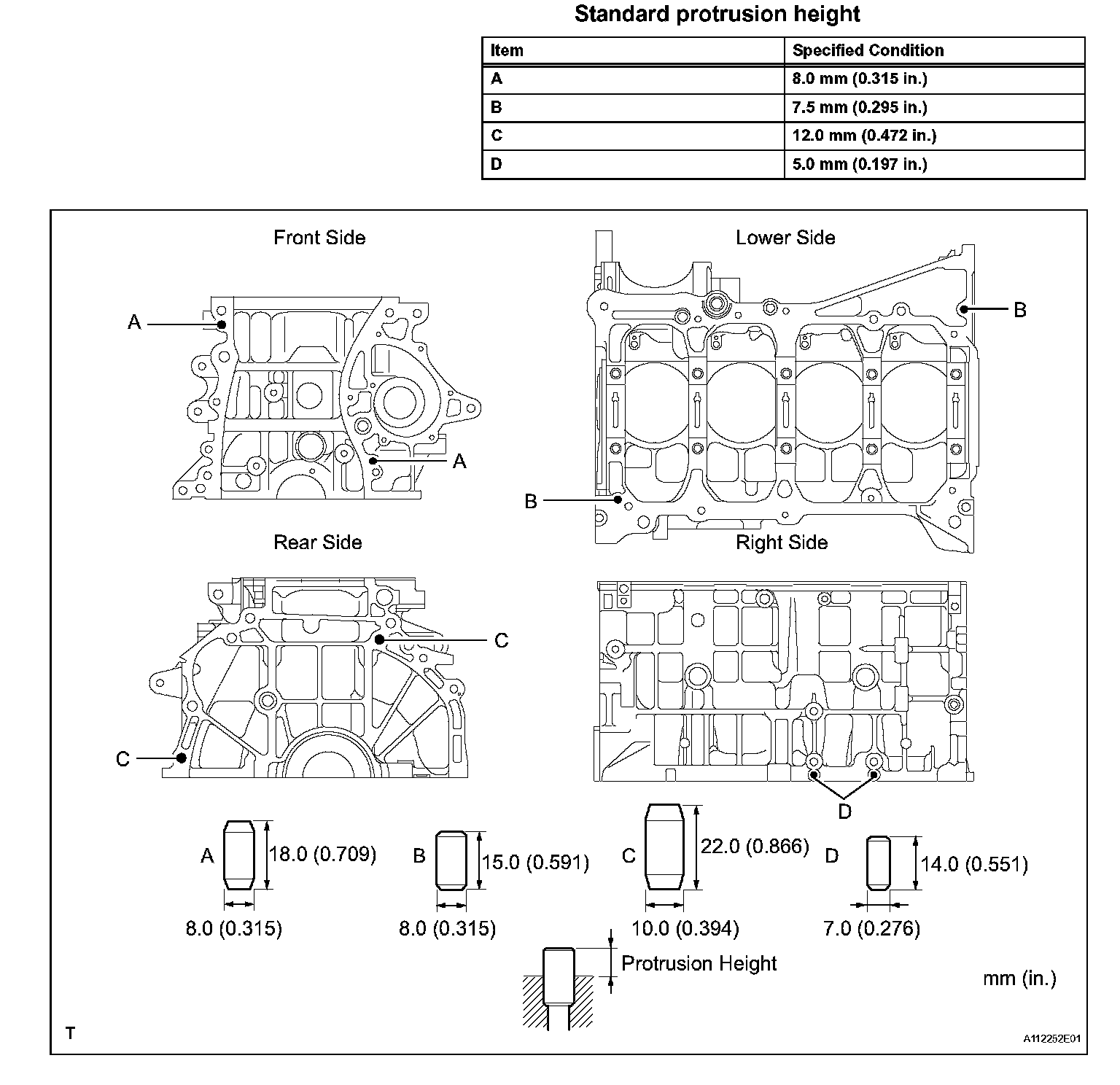
b. Using a plastic-faced hammer, install 8 new straight pins.