Part 1
ENGINE UNITEngine Unit Components:
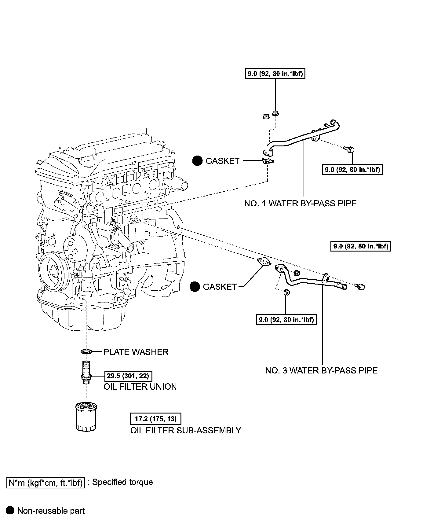
Engine Unit Components:
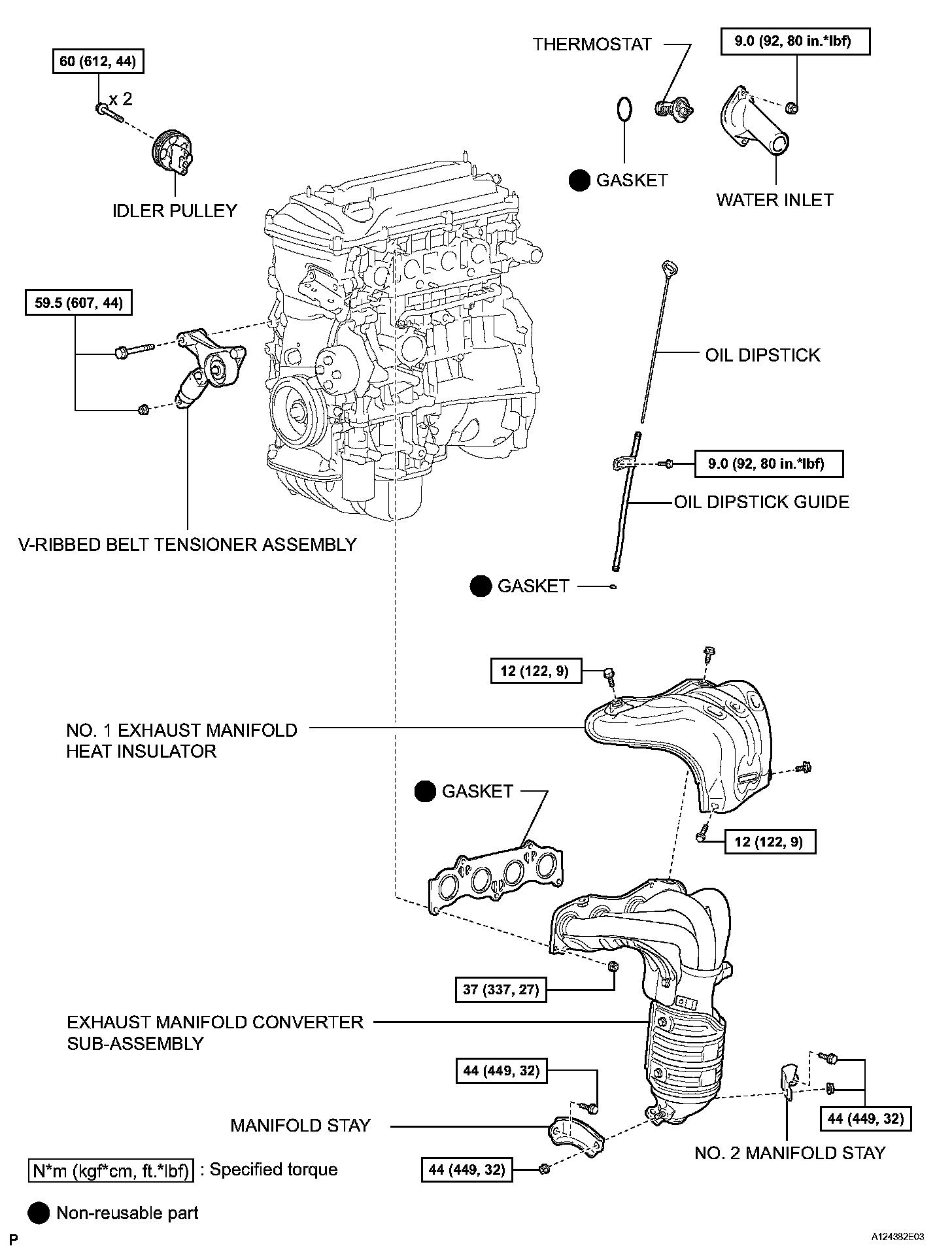
Engine Unit Components:
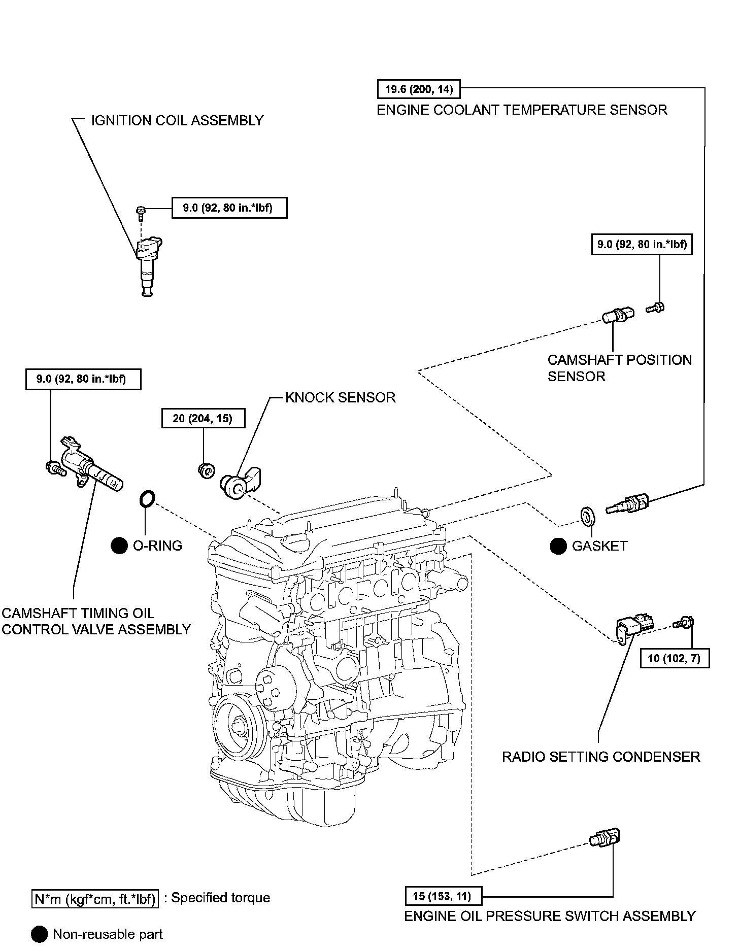
Engine Unit Components:
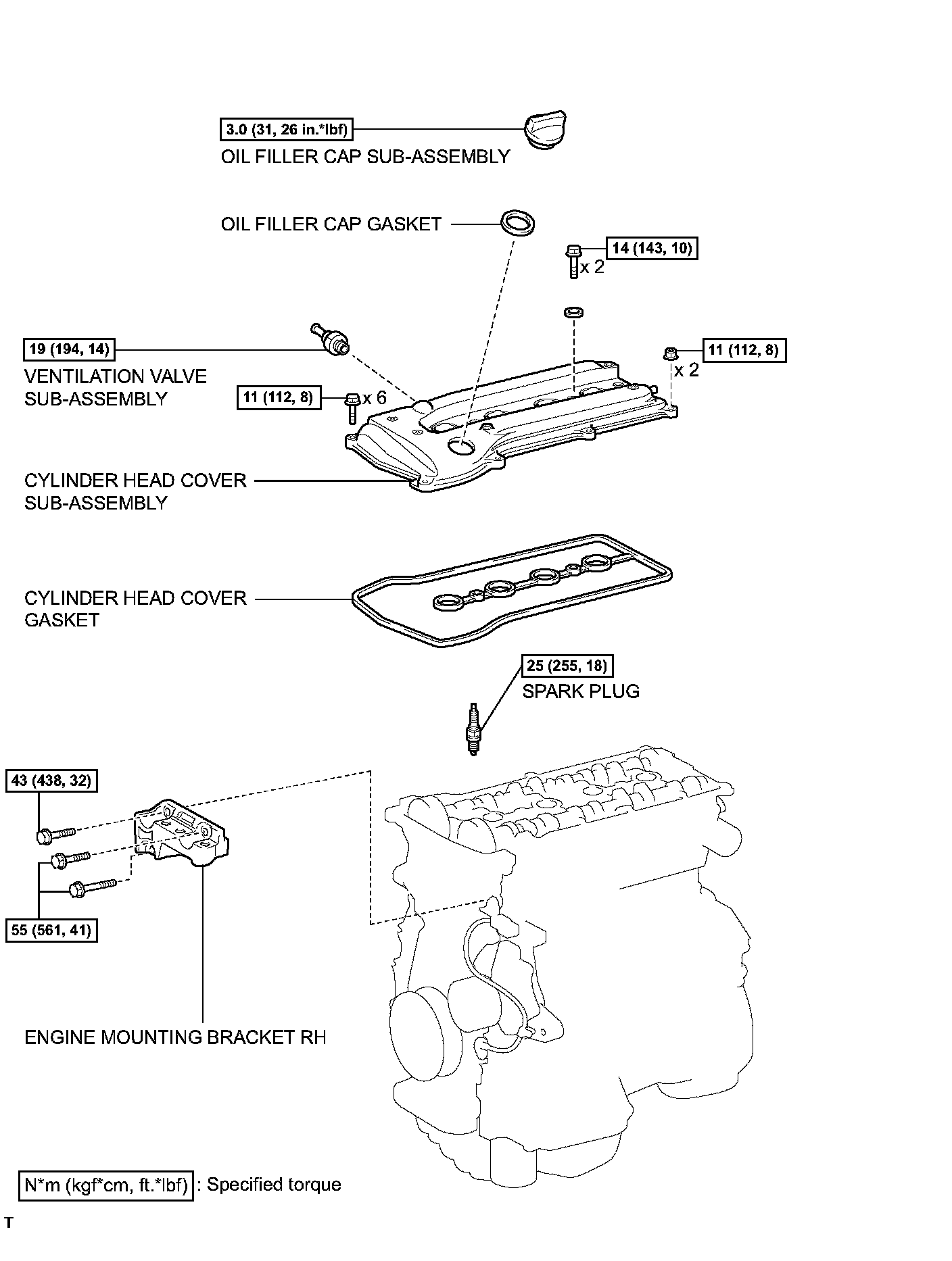
Engine Unit Components:
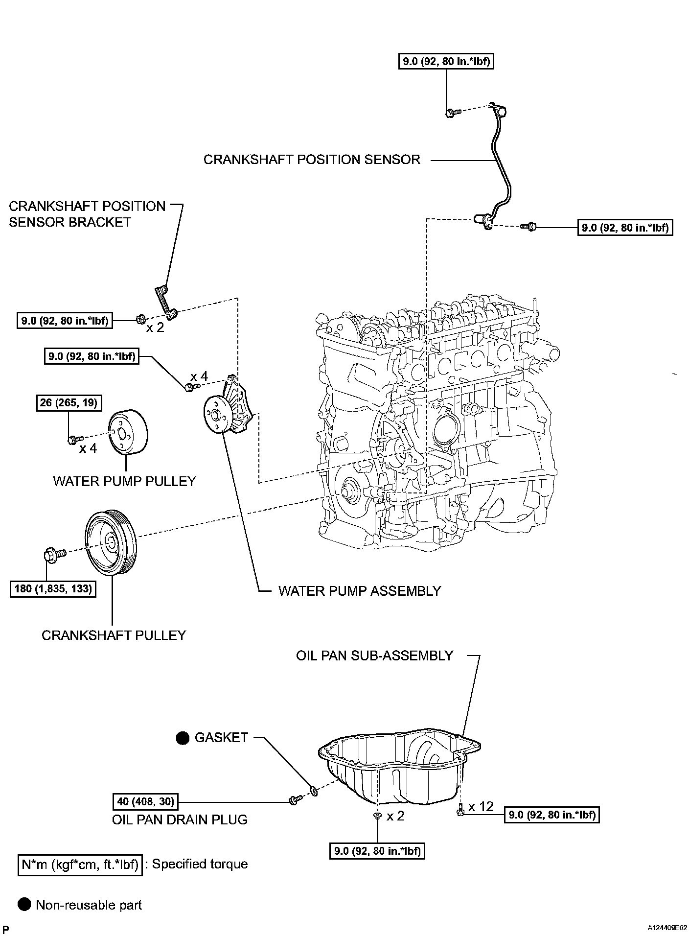
Engine Unit Components:
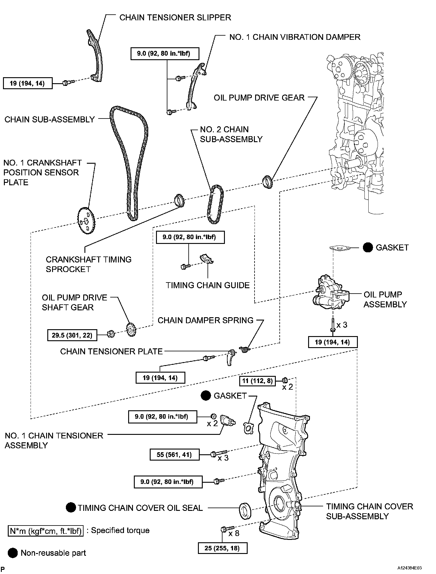
Engine Unit Components:
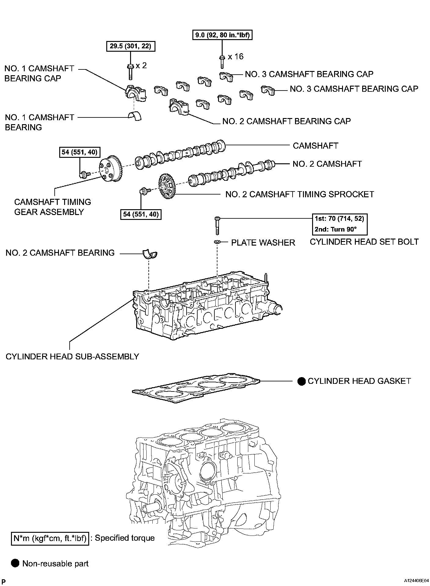
Engine Unit Components:
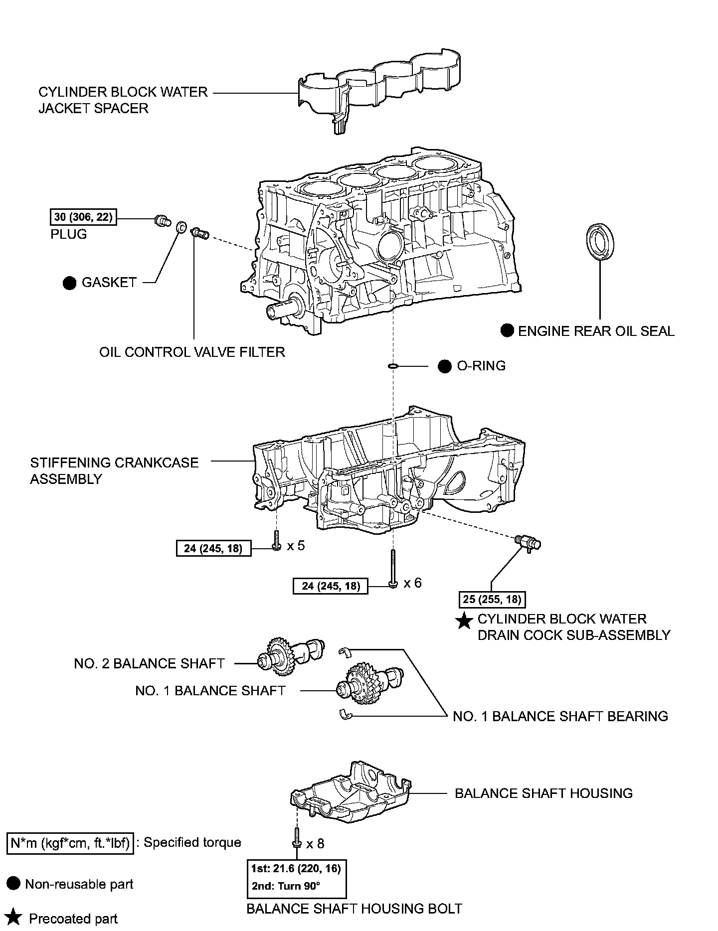
Engine Unit Components:
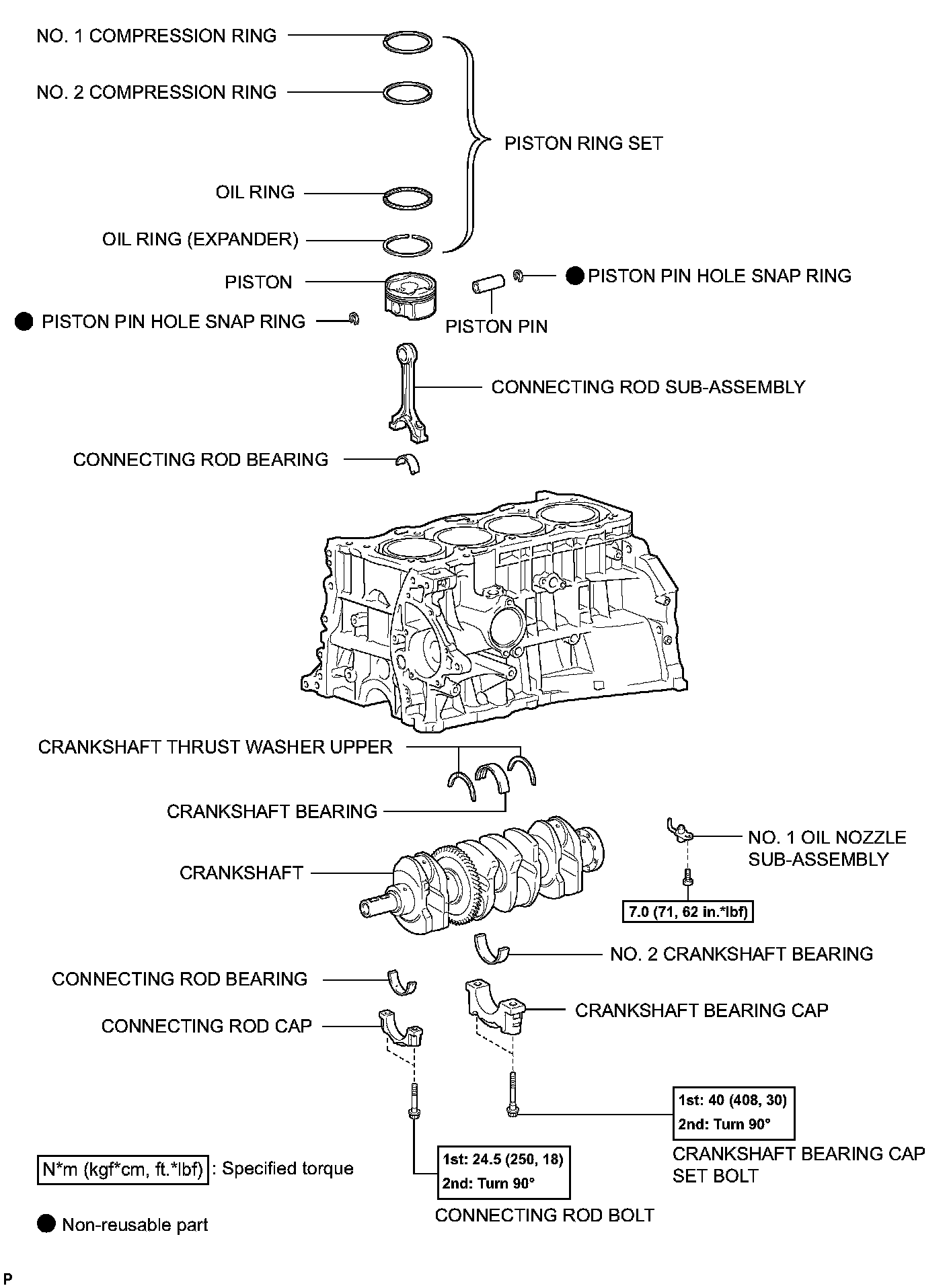
REASSEMBLY
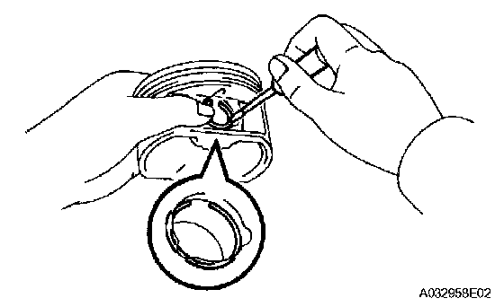
1. INSTALL PISTON
a. Using a small screwdriver, install a new snap ring onto one end of the piston pin hole.
HINT: Make sure that the end gap of the snap ring is not aligned with the pin hole cutout portion of the piston.
b. Gradually heat the piston up to 80 to 90°C (176 to 194°F).
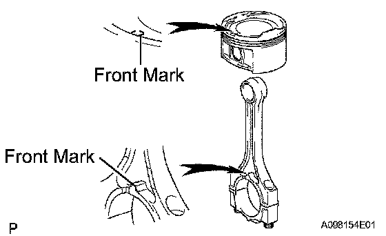
c. Align the front marks of the piston and connecting rod, then push in the piston pin with your thumb until the pin comes into contact with the snap pin hole.
HINT: Make sure that the end gap of the snap ring is not aligned with the pin hole cutout portion of the piston.
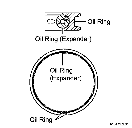
2. INSTALL PISTON RING SET
a. Install the expander and oil ring by hand.
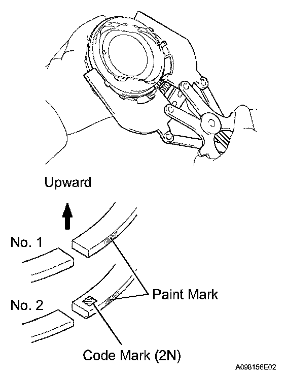
b. Using a piston ring expander, install the 2 compression rings with the paint mark as shown in the illustration.
NOTICE: Install the No. 2 compression ring with the code mark (2N) facing upward.
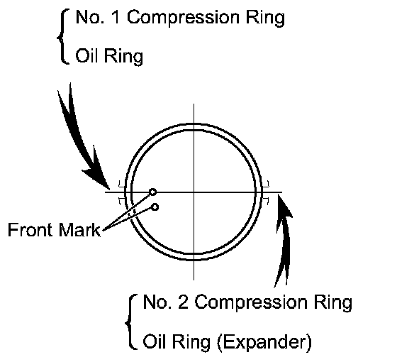
c. Position the piston rings so that the ring ends are as shown in the illustration.
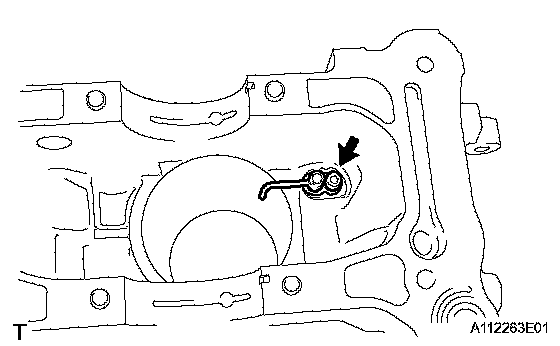
3. INSTALL NO. 1 OIL NOZZLE SUB-ASSEMBLY
a. Install the 4 oil nozzles with the 4 bolts.
Torque: 7.0 Nm (71 kgf-cm, 62 inch lbs.)
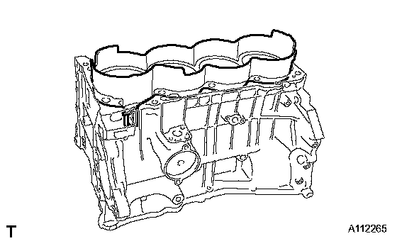
4. INSTALL CYLINDER BLOCK WATER JACKET SPACER
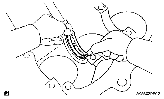
5. INSTALL CRANKSHAFT BEARING
a. Install the upper bearing with an oil groove onto the cylinder block.
NOTICE: Do not apply engine oil to the contact surfaces of the cylinder block and crankshaft bearing.
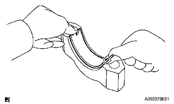
6. INSTALL NO. 2 CRANKSHAFT BEARING
a. Install the lower bearing onto the bearing cap.
NOTICE: Do not apply engine oil to the contact surfaces of the cylinder block and crankshaft bearing cap.
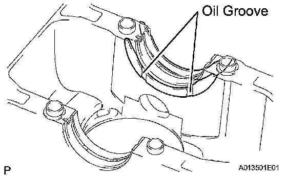
7. INSTALL CRANKSHAFT THRUST WASHER UPPER
a. Install the 2 thrust washers onto the No. 3 journal position of the cylinder block with the oil groove facing outward.
8. INSTALL CRANKSHAFT
a. Apply engine oil to the upper bearing, and install the crankshaft onto the cylinder block.
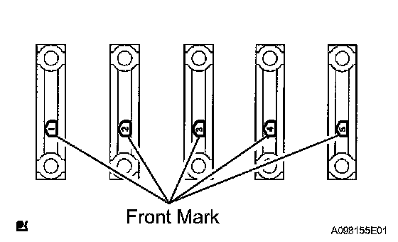
b. Examine the front marks and numbers, and install the bearing caps onto the cylinder block in the order shown in the illustration.
c. Apply a light coat of engine oil to the threads and under the heads of the bearing cap bolts.

d. Using several steps, uniformly install and tighten the 10 bearing cap bolts in the sequence shown in the illustration.
Torque: 40 Nm (408 kgf-cm, 30 ft. lbs.)
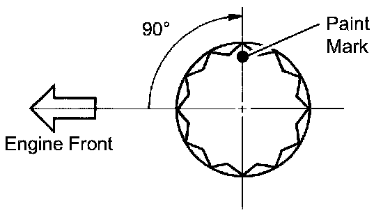
e. Mark the front of the bearing cap bolts with paint.
f. Retighten the 10 bearing cap bolts by 90° in the same sequence.
g. Check that the paint marks are now at a 90° angle to the front.
h. Check that the crankshaft turns smoothly

9. INSTALL CONNECTING ROD BEARING
a. Align the bearing claw with the oil groove of the connecting rod or connecting rod cap.
NOTICE:
^ Do not apply engine oil to the contact surfaces of the connecting rod cap and bearing.
^ Do not apply engine oil to the contact surfaces of the connecting rod and bearing.
10. INSTALL PISTON WITH CONNECTING ROD
a. Apply engine oil to the cylinder walls, pistons, and surfaces of connecting rod bearings.
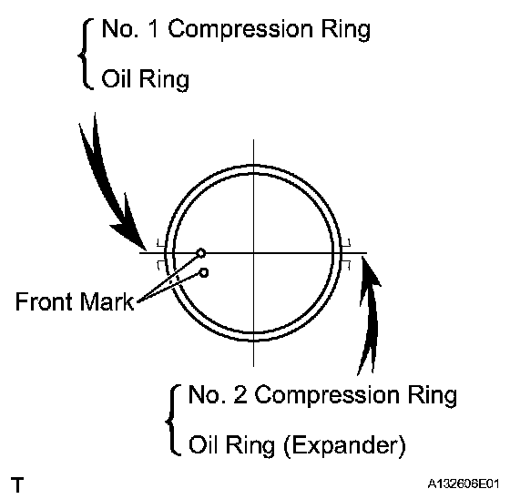
b. Check the position of the piston ring ends.
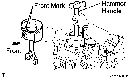
c. Using a hammer handle and piston ring compressor, press a piston and connecting rod into each cylinder with the front mark of the piston facing forward.
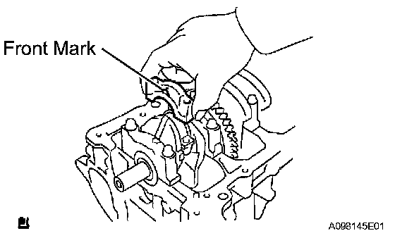
d. Check that the front mark of the connecting rod cap is facing in the correct direction.
NOTICE: Match the numbered connecting rod cap with the connecting rod.
e. Apply a light coat of engine oil to the threads and under the heads of the connecting rod bolts.
f. Using a 12 mm socket wrench, tighten the bolts in several passes to the specified torque.
Torque: 24.5 Nm (250 kgf-cm, 18 ft. lbs.)
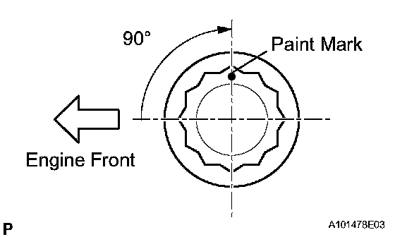
g. Mark the front of the connecting rod bolts with paint.
h. Retighten the cap bolts 90° as shown in the illustration.
i. Check that the crankshaft turns smoothly.
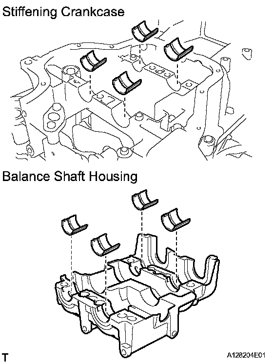
11. INSTALL NO. 1 BALANCE SHAFT BEARING
a. Align the bearing claw with the claw groove, and push in the 8 bearings.
NOTICE:
^ Do not apply engine oil to the contact surfaces of the balance shaft bearing and balance shaft housing.
^ Do not apply engine oil to the contact surfaces of the balance shaft bearing and stiffening crankcase.
b. Apply light coat of engine oil to the bearings.
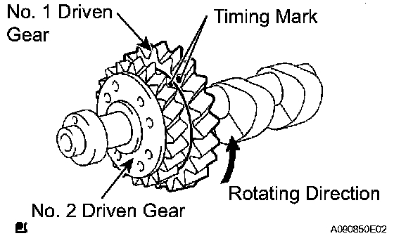
12. INSTALL BALANCE SHAFT
a. Rotate the No. 1 driven gear of the No. 1 balance shaft in the rotating direction until it hits the stopper.
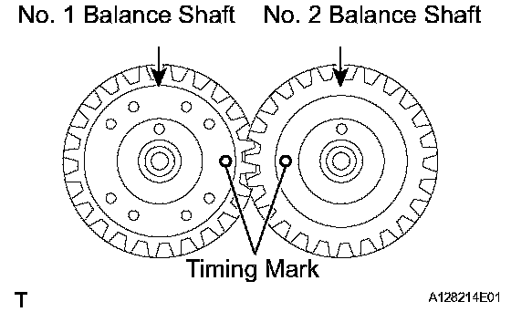
b. Confirm that the timing marks on the No. 1 and No. 2 driven gears are aligned.
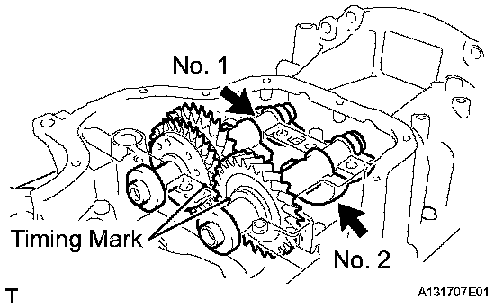
c. Align the timing marks of the No. 1 and No. 2 balance shafts as shown in the illustration.
d. Place the No. 1 and No. 2 balance shafts onto the crankcase.
e. Apply a light coat of engine oil to the threads and under the heads of the bolts.
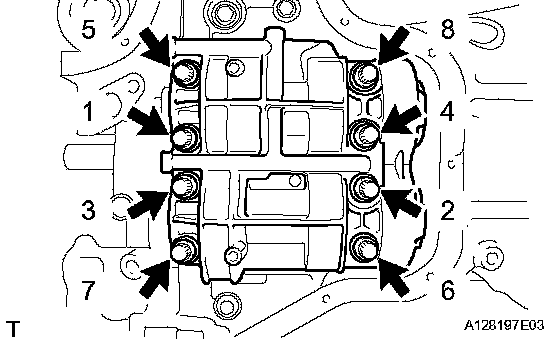
f. Using several steps, uniformly install and tighten the 8 bolts in the sequence shown in the illustration.
Torque: 21.6 Nm (220 kgf-cm, 16 ft. lbs.)
g. Mark the front of the bolts with paint.
h. Retighten the bolts 90° as shown in the illustration.
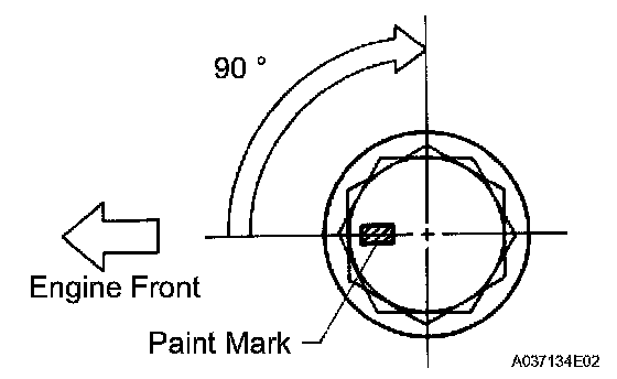
i. Check that the paint mark is now at a 90° angle to the front.
13. INSTALL STIFFENING CRANKCASE ASSEMBLY
a. Remove any old packing material and be careful not to drop any oil on the contact surfaces of the cylinder block and crankcase.
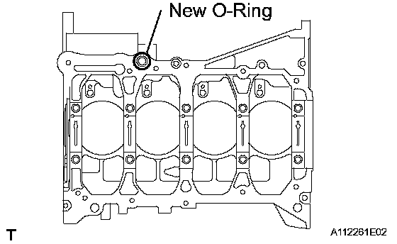
b. Place a new O-ring on the cylinder block as shown in the illustration.
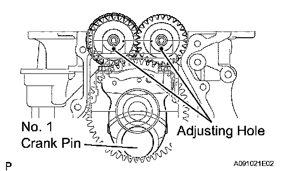
c. With the No. 1 crank pin of the crankshaft placed at the 6 o'clock position, install the No. 1 and No. 2 balance shafts and align the adjusting holes as shown in the illustration.
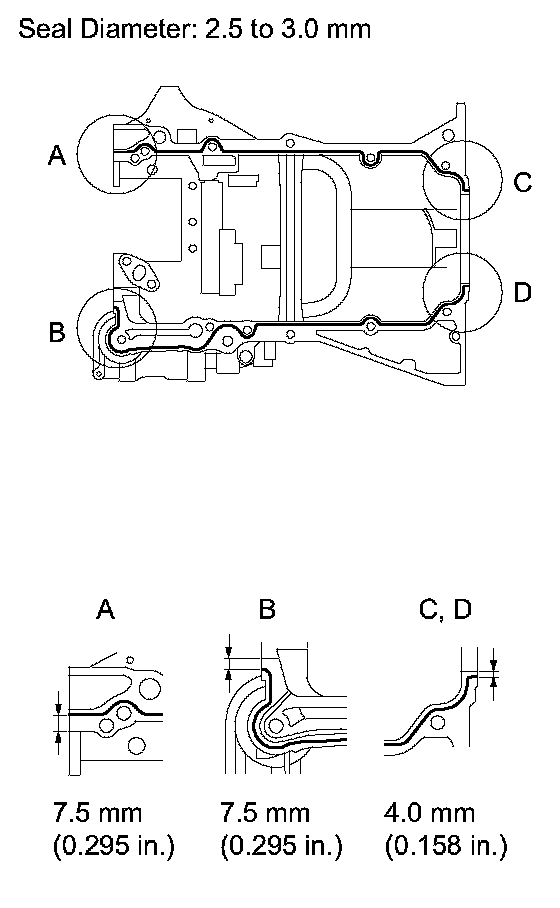
d. Apply a continuous bead of seal packing (Diameter 2.5 to 3.0 mm (0.098 to 0.118 inch)) as shown in the illustration.
Seal packing: Toyota Genuine Seal Packing Black, Three Bond 1207B or equivalent
NOTICE:
^ Remove any oil from the contact surface.
^ Install the crankcase within 3 minutes of applying seal packing.
^ Do not add engine oil for at least 2 hours after installing the crankcase.
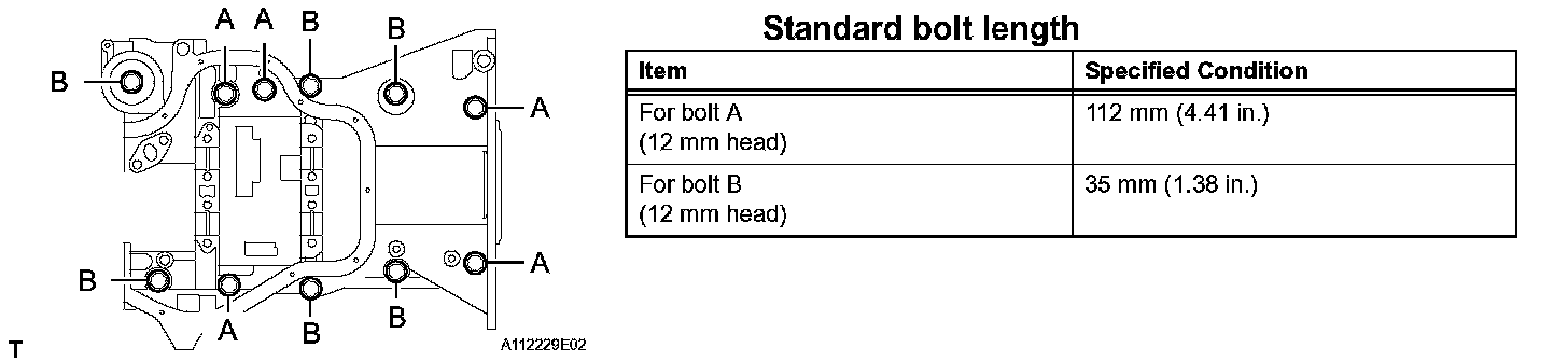
e. Temporarily install the crankcase with the 11 bolts.
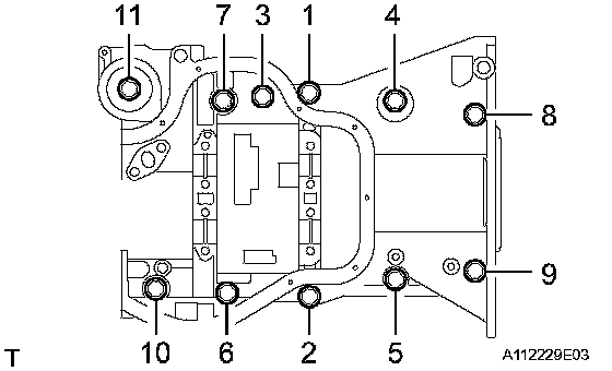
f. Uniformly tighten the bolts.
Torque: 24 Nm (245 kgf-cm, 18 ft. lbs.)
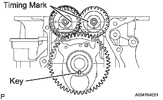
g. Confirm that the timing marks of the balance shafts are aligned when the key groove is placed at the 6 o'clock position, as shown in the illustration.
14. INSTALL ENGINE REAR OIL SEAL
a. Apply multi-purpose grease to the lip of a new oil seal.
NOTICE: Keep the lip free of foreign object.
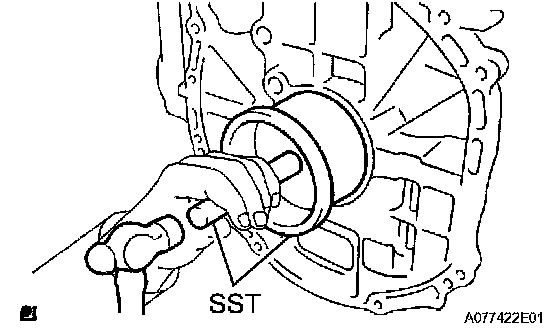
b. Using SST and hammer, tap in the new oil seal until its surface is flush with the rear oil seal retainer edge.
SST 09223-15030, 09950-70010 (09951-07100)
NOTICE:
^ Wipe any extra grease off the crankshaft.
^ Do not tap the oil seal at an angle.
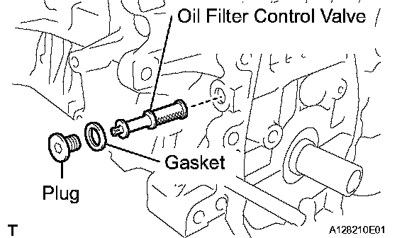
15. INSTALL OIL CONTROL VALVE FILTER
a. Check that there are no foreign objects on the mesh part of the oil control valve filter.
b. Using a 6 mm socket hexagon wrench, install a new gasket and the oil control valve filter with the plug.
Torque: 30 Nm (306 kgf-cm, 22 ft. lbs.)
16. INSTALL CYLINDER BLOCK WATER DRAIN COCK SUB-ASSEMBLY
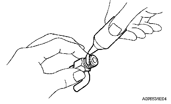
a. Apply adhesive to 2 or 3 threads of the drain cock.
Adhesive: Toyota Genuine Adhesive 1324, Three Bond 1324 or equivalent
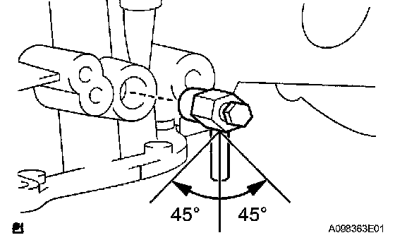
b. After tightening the drain cock to the specified torque, turn the drain cock clockwise as shown in the illustration.
Torque: 25 Nm (255 kgf-cm, 18 ft. lbs.)
NOTICE:
^ Install the drain cock within 3 minutes of applying adhesive.
^ Do not add coolant for at least an hour after installing the drain cock.
^ Do not turn the drain cock by more than 1 revolution (360°) after tightening the drain cock to the specified torque.
^ Do not loosen the drain cock after setting it correctly.
17. INSTALL CYLINDER HEAD GASKET
18. INSTALL CYLINDER HEAD SUB-ASSEMBLY
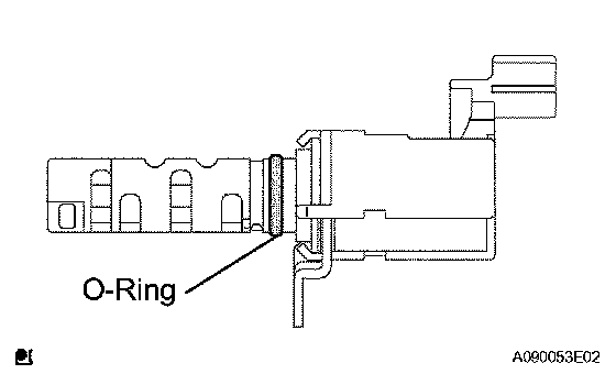
19. INSTALL CAMSHAFT TIMING OIL CONTROL VALVE ASSEMBLY
a. Apply a light coat of engine oil to a new O-ring, then install it onto the camshaft timing oil control valve.
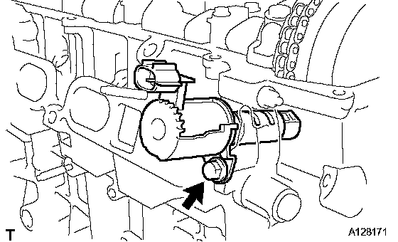
b. Install the camshaft timing oil control valve with the bolt.
Torque: 9.0 Nm (92 kgf-cm, 80 inch lbs.)
20. INSTALL CAMSHAFT TIMING GEAR ASSEMBLY
21. INSTALL NO. 2 CAMSHAFT TIMING SPROCKET
22. INSTALL NO. 2 CAMSHAFT BEARING
23. INSTALL NO. 1 CAMSHAFT BEARING
24. INSTALL CAMSHAFT
25. INSTALL OIL PUMP ASSEMBLY
26. INSTALL OIL PUMP DRIVE GEAR
27. INSTALL NO. 2 CHAIN SUB-ASSEMBLY
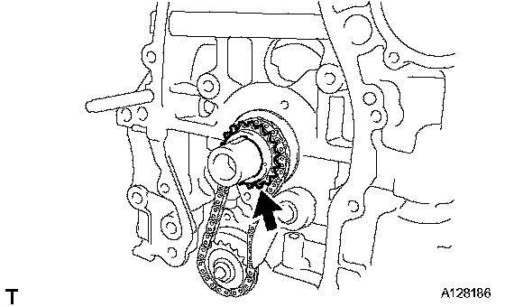
28. INSTALL CRANKSHAFT TIMING SPROCKET
29. INSTALL NO. 1 CHAIN VIBRATION DAMPER
30. INSTALL CHAIN SUB-ASSEMBLY
31. INSTALL CHAIN TENSIONER SLIPPER
32. INSTALL TIMING CHAIN GUIDE
33. INSTALL NO. 1 CRANKSHAFT POSITION SENSOR PLATE
34. REPLACE TIMING CHAIN COVER OIL SEAL
35. INSTALL TIMING CHAIN COVER SUB-ASSEMBLY
36. INSTALL NO. 1 CHAIN TENSIONER ASSEMBLY
37. INSTALL CRANKSHAFT PULLEY
38. INSTALL OIL PAN SUB-ASSEMBLY
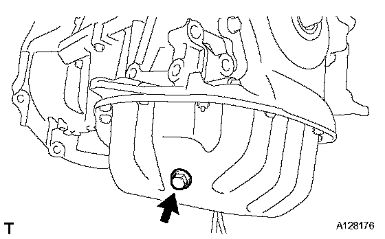
39. INSTALL OIL PAN DRAIN PLUG
a. Place a new gasket on the oil pan drain plug, then install it onto the oil pan.
Torque: 40 Nm (408 kgf-cm, 30 ft. lbs.)
40. INSTALL WATER PUMP ASSEMBLY