Shift Interlock: Service and Repair
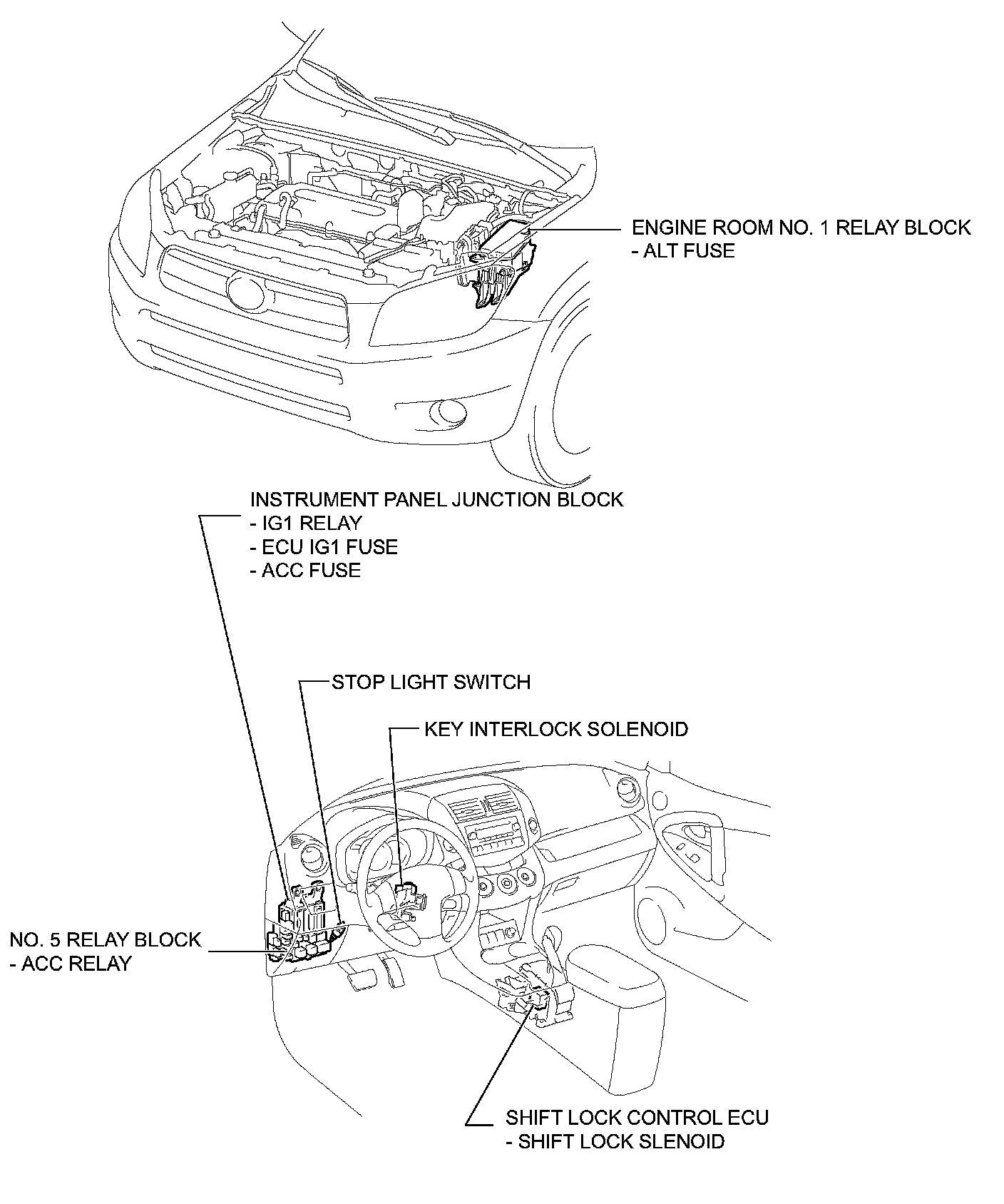
SHIFT LOCK SYSTEMParts Location:
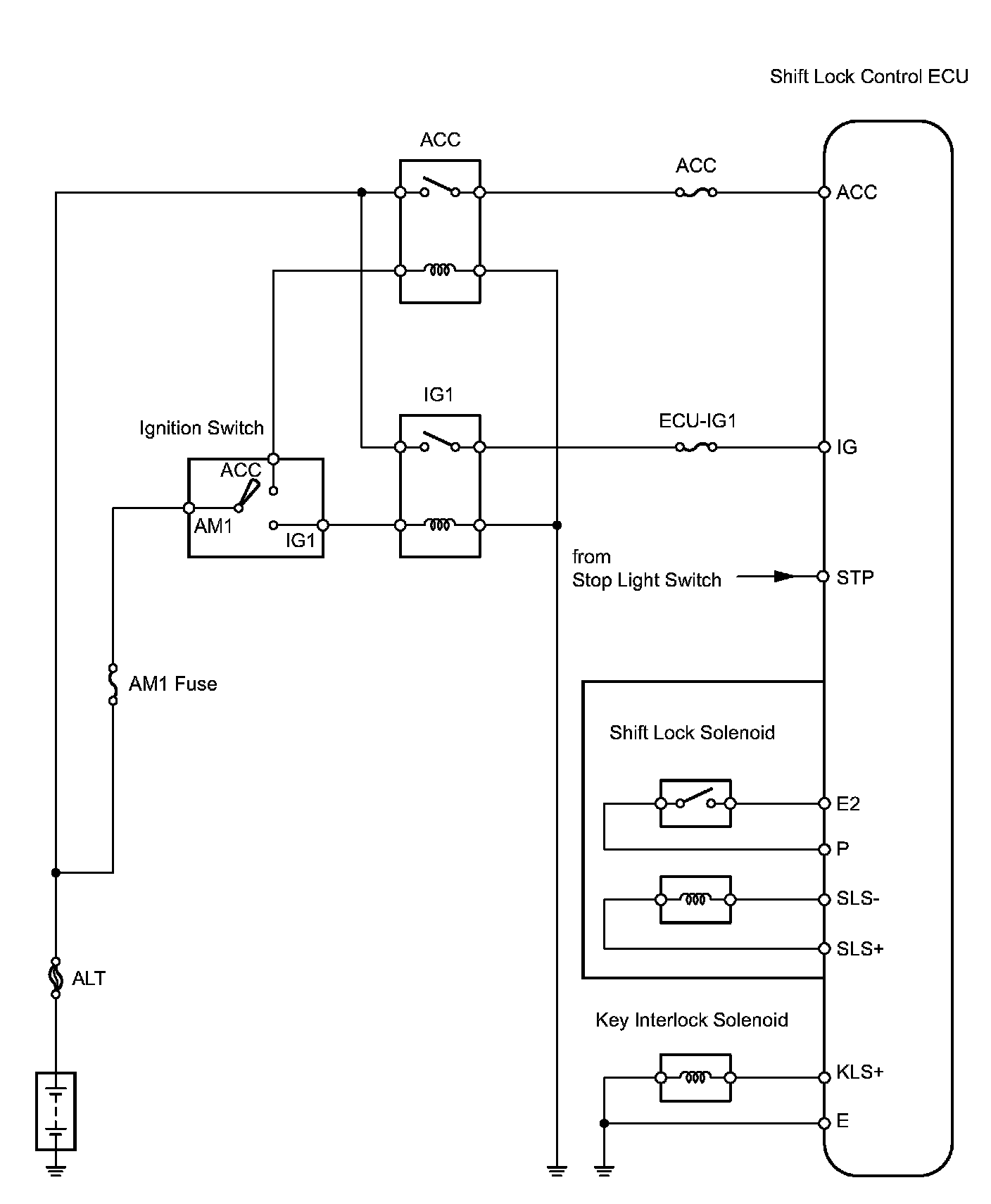
System Diagram:
ON-VEHICLE INSPECTION
1. CHECK SHIFT LOCK OPERATION
a. Move the shift lever to R
b. Turn the ignition switch OFF.
c. Check that the shift lever cannot be moved to any position other than P.
d. Turn the ignition switch ON, depress the brake pedal and check that the shift lever can be moved to other positions.
2. CHECK SHIFT LOCK RELEASE BUTTON OPERATION
a. When operating the shift lever with the shift lock release button pressed, check that the lever can be moved to any position other than R If the operation cannot be performed as specified, check the shift lever assembly.
3. REMOVE KEY INTERLOCK OPERATION
a. Turn the ignition switch ON.
b. Depress the brake pedal and move the shift lever to any position other than P.
c. Check that the ignition switch cannot be turned OFF.
d. Move the shift lever to P, turn the ignition switch OFF and check that the key can be removed. If the results are not as specified, inspect the shift lock control unit.
4. CHECK SHIFT LOCK CONTROL UNIT ASSEMBLY
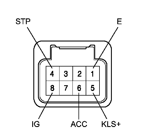
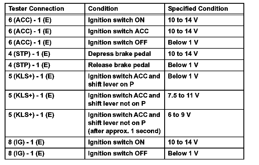
a. Measure the voltage of the connector.
HINT: Do not disconnect the shift lock control ECU connector.
Standard Voltage:
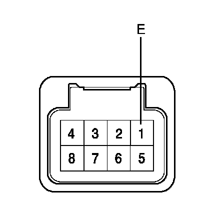
b. Measure the resistance of the connector.
HINT: Do not disconnect the shift lock control ECU connector.
Standard Resistance:

If the result is not as specified, replace the shift lock control ECU.
INSPECTION
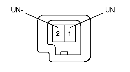
1. INSPECT KEY INTERLOCK SOLENOID
a. Disconnect the solenoid connector.
b. Connect the battery's positive (+) lead to terminal 1 (UN+) and the battery's negative (-) lead to terminal 2 (UN-). Check that the operating noise of the solenoid can be heard. If the result is not as specified, replace the solenoid.