Part 1
ENGINE ASSEMBLYCOMPONENTS:
COMPONENTS:
COMPONENTS:
COMPONENTS:
COMPONENTS:
COMPONENTS:
COMPONENTS:
COMPONENTS:
COMPONENTS:
COMPONENTS:
COMPONENTS:
INSTALLATION (STEPS 1-27)
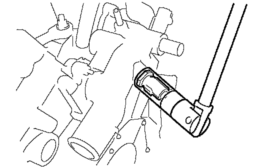
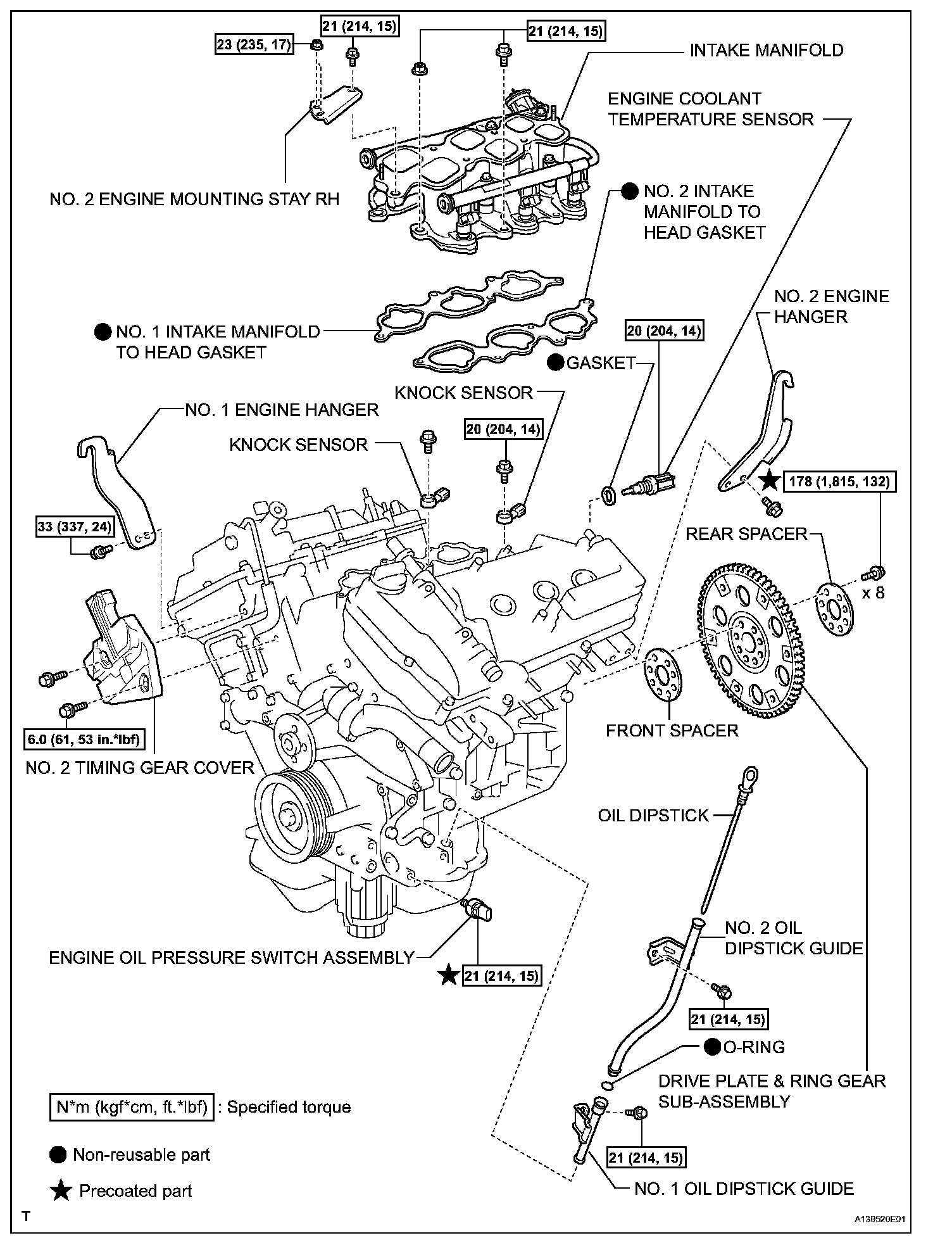
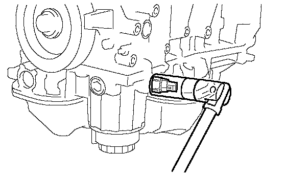
1. INSTALL ENGINE COOLANT TEMPERATURE SENSOR
a. Using a 19 mm deep socket wrench, install the sensor and a new gasket.
Torque: 20 Nm (204 kgf-cm, 14 ft. lbs.)
2. INSTALL KNOCK SENSOR
3. INSTALL ENGINE OIL PRESSURE SWITCH ASSEMBLY
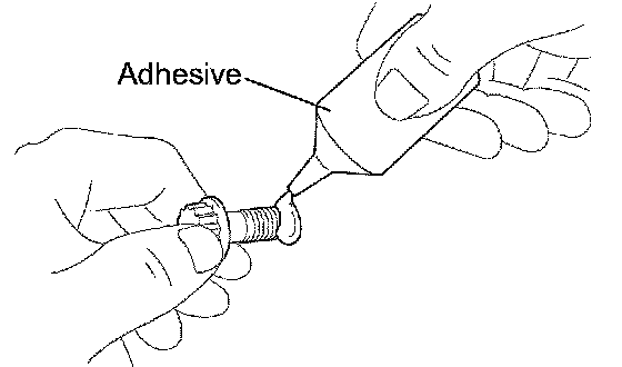
a. Clean the threads of the oil pressure switch. Apply adhesive to 2 or 3 threads of the oil pressure switch.
Adhesive: Toyota Genuine Adhesive 1344, Three Bond 1344 or Equivalent
b. Using a 24 mm deep socket wrench, install the oil pressure switch.
Torque: 21 Nm (214 kgf-cm, 15 ft. lbs.)
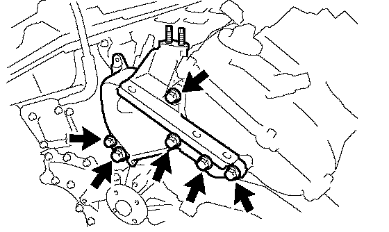
4. INSTALL NO. 1 FRONT ENGINE MOUNTING BRACKET LH
a. Install the mounting bracket with the 6 bolts.
Torque: 54 Nm (551 kgf-cm, 40 ft. lbs.)
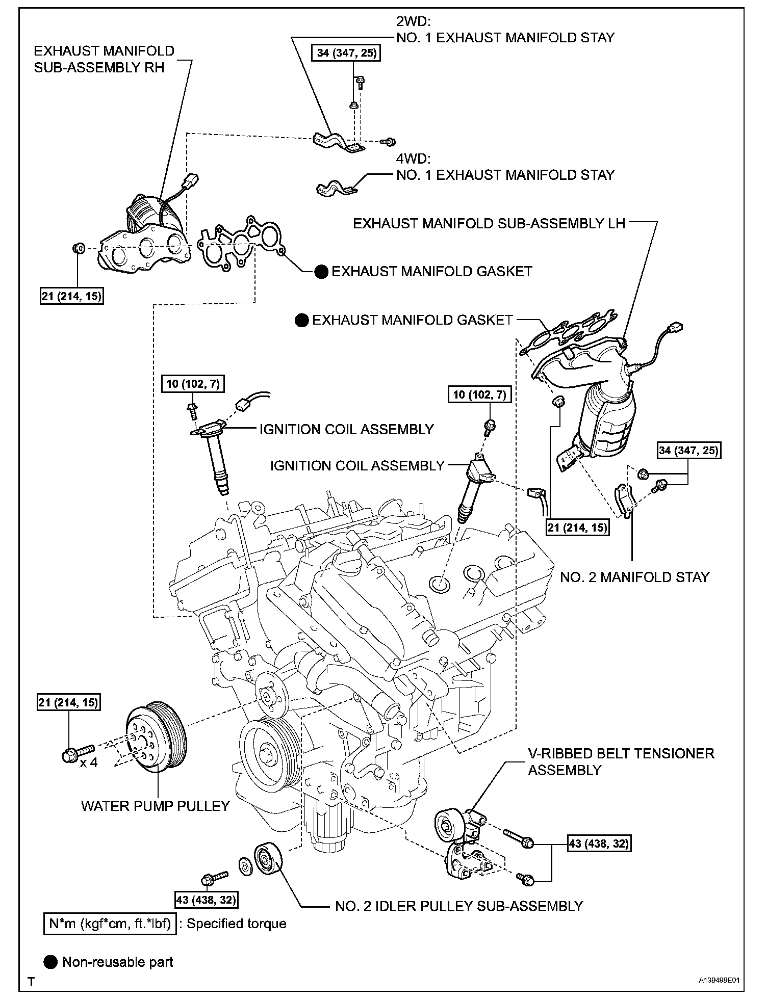
5. INSTALL WATER PUMP PULLEY
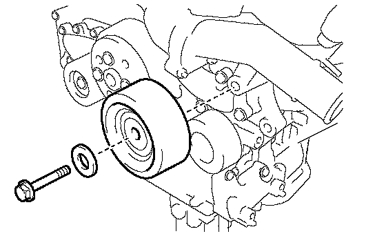
6. INSTALL NO. 2 IDLER PULLEY SUB-ASSEMBLY
a. Install the idler pulley and cover plate with the bolt.
Torque: 43 Nm (438 kgf-cm, 32 ft. lbs.)
7. INSTALL NO. 2 TIMING GEAR COVER
a. Install the gear cover with the 2 bolts.
Torque: 6.0 Nm (61 kgf-cm, 53 inch lbs.)
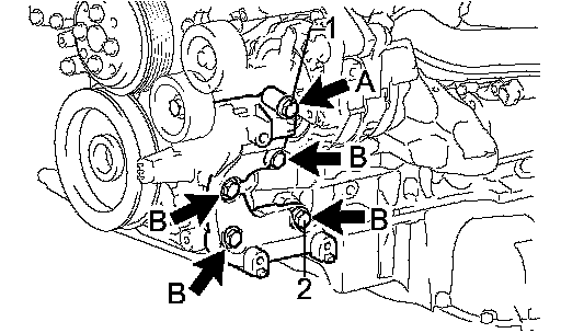
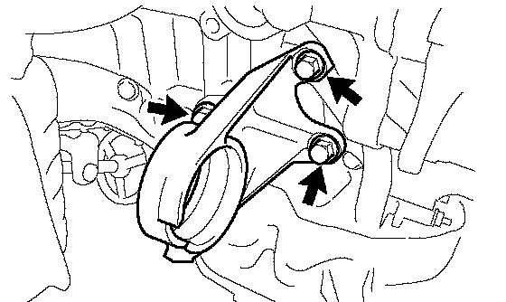
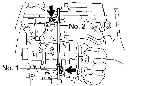
8. INSTALL V-RIBBED BELT TENSIONER ASSEMBLY
a. Temporarily install the V-ribbed belt tensioner with the 5 bolts.
b. Install the V-ribbed belt tensioner by tightening the bolt 1 and bolt 2 in the order shown in the illustration.
Torque: 43 Nm (438 kgf-cm, 32 ft. lbs.)
c. Tighten the other bolts.
Torque: 43 Nm (438 kgf-cm, 32 ft. lbs.)
Each bolt length is as follows:
Each bolt length is as follows::

Each bolt length is as follows::

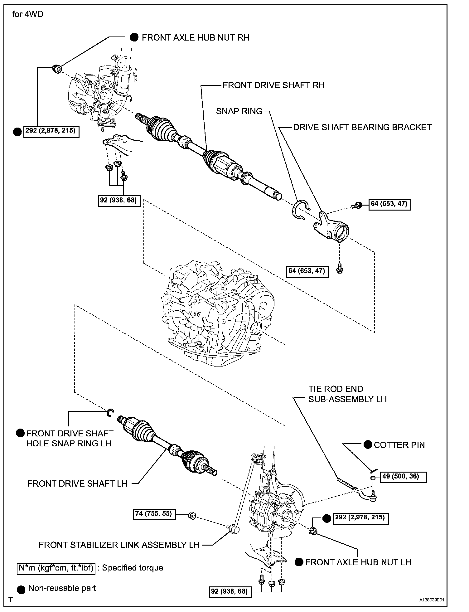
9. INSTALL DRIVE SHAFT BEARING BRACKET
a. Install the drive shaft bearing bracket with the 3 bolts.
Torque: 64 Nm (653 kgf-cm, 47 ft. lbs.)
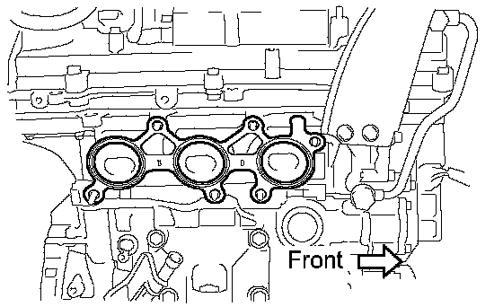
10. INSTALL EXHAUST MANIFOLD SUB-ASSEMBLY LH
a. Install a new gasket as shown in the illustration.
b. Install the manifold with the 6 nuts.
Torque: 21 Nm (214 kgf-cm, 15 ft. lbs.)
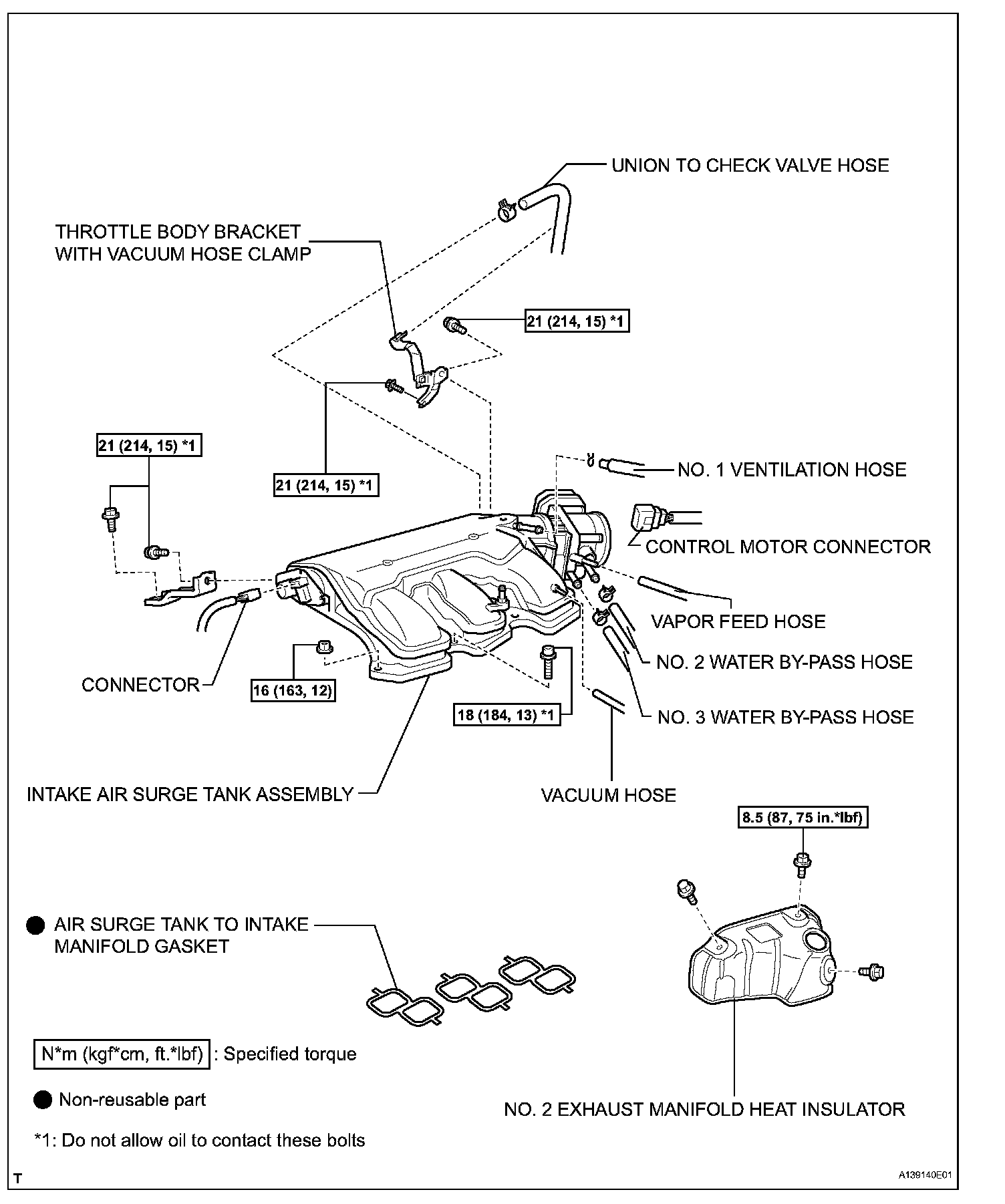
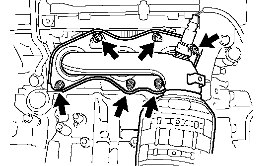
11. INSTALL NO. 2 EXHAUST MANIFOLD HEAT INSULATOR
a. Install the No. 2 heat insulator with the 3 bolts.
Torque: 8.5 Nm (87 kgf-cm, 75 inch lbs.)
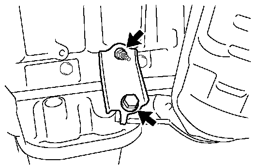
12. INSTALL NO. 2 MANIFOLD STAY
a. Install the No. 2 manifold stay with the bolt and nut.
Torque: 34 Nm (347 kgf-cm, 25 ft. lbs.)
13. INSTALL OIL DIPSTICK GUIDE
a. Install 2 new O-rings to the guide.
b. Apply a light coat of engine oil to the O-rings.
c. Push in the guide end into the guide hole.
d. Install the No. 1 guide with the bolt.
Torque: 21 Nm (214 kgf-cm, 15 ft. lbs.)
e. Install the No. 2 guide with the bolt.
Torque: 21 Nm (214 kgf-cm, 15 ft. lbs.)
f. Install the dipstick.
14. INSTALL GENERATOR ASSEMBLY
15. INSTALL COMPRESSOR WITH PULLEY ASSEMBLY
16. INSTALL FAN AND GENERATOR V BELT
17. INSTALL EXHAUST MANIFOLD SUB-ASSEMBLY RH
a. Install a new gasket as shown in the illustration.
b. Install the manifold with the 6 nuts.
Torque: 21 Nm (214 kgf-cm, 15 ft. lbs.)
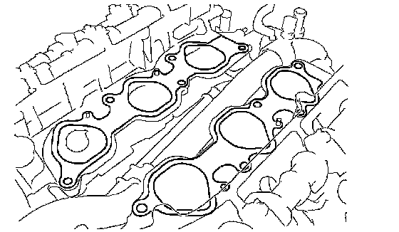
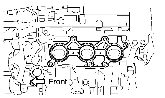
18. INSTALL INTAKE MANIFOLD
a. Set a new gasket on each cylinder head.
NOTICE:
^ Align the port holes of the gasket and cylinder head.
^ Be careful of the installation direction.
b. Set the intake manifold on the cylinder heads.
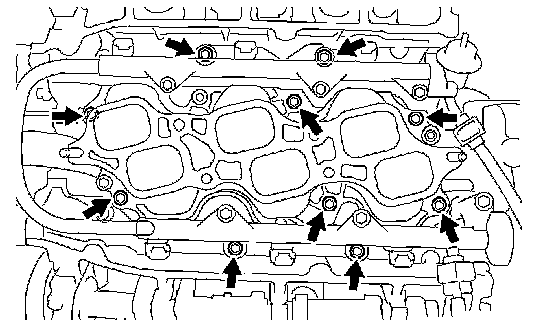
c. Install and uniformly tighten the 6 bolts and 4 nuts in several passes.
Torque: 21 Nm (214 kgf-cm, 15 ft. lbs.)
d. Connect the 6 fuel injector connectors.
19. INSTALL FUEL INJECTOR ASSEMBLY
20. INSTALL NO. 2 ENGINE MOUNTING STAY RH
a. Install the mounting stay with the bolt.
Torque: 21 Nm (214 kgf-cm, 15 ft. lbs.)
21. INSTALL IGNITION COIL ASSEMBLY
a. Install the 6 ignition coils with the 6 bolts to the cylinder head.
Torque: 10 Nm (102 kgf-cm, 7 ft. lbs.)
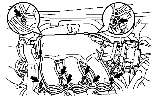
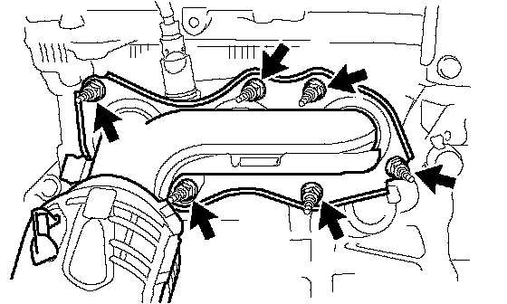
22. INSTALL INTAKE AIR SURGE TANK ASSEMBLY
NOTICE: Make sure there is no oil on the bolts. If there is oil on the bolts, clean them before installing them.
a. Install a new gasket to the surge tank.
b. Using a 5 mm hexagon socket wrench, install the 4 bolts.
Torque: 18 Nm (184 kgf-cm, 13 ft. lbs.)
c. Install the surge tank with the 2 nuts and 2 bolts.
Torque:
21 Nm (214 kgf-cm, 15 ft. lbs.) for bolt
16 Nm (163 kgf-cm, 12 ft. lbs.) for nut
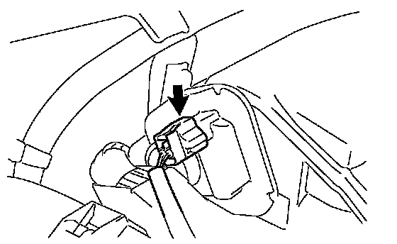
d. Connect the connector.
e. Install the vacuum hose clamp with the bolt.
Torque: 5.4 Nm (55 kgf-cm, 48 inch lbs.)
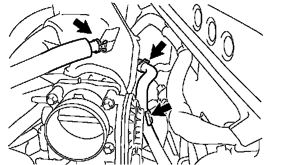
f. Connect the union to check valve hose.
g. Connect the No. 2 ventilation hose.
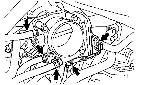
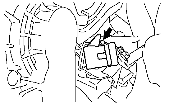
h. Install the clamp and connect the throttle body connector.
i. Connect the vapor feed hose.
j. Connect the 2 water by-pass hoses to the throttle body.
23. REMOVE ENGINE FROM ENGINE STAND
a. Install a sling device and chain block to the engine.
b. Remove the engine from the engine stand.
24. INSTALL DRIVE PLATE AND RING GEAR SUBASSEMBLY
a. Clean the bolt and its hole.
b. Apply adhesive to 2 or 3 threads of the bolt end.
Adhesive: Toyota Genuine Adhesive 1324, Three Bond 1324 or Equivalent
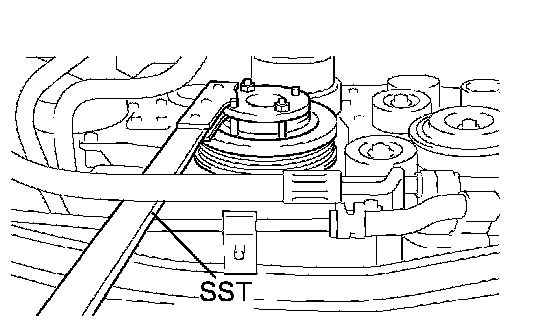
c. Using SST, hold the crankshaft.
SST 09213-70011, 09330-00021
d. Install the flywheel, drive plate and drive plate spacer on the crankshaft.

e. Uniformly install and tighten the 8 bolts.
Torque: 178 Nm (1,815 kgf-cm, 132 ft. lbs.)
NOTICE: Do not start the engine for at least 1 hour after the installation.
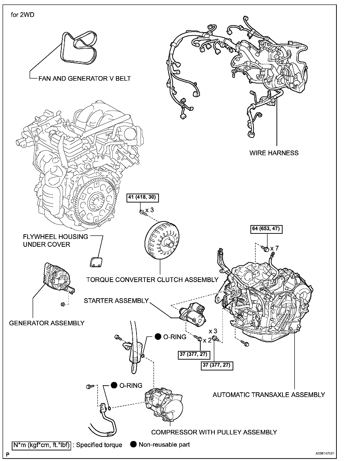
25. INSTALL AUTOMATIC TRANSAXLE ASSEMBLY
a. 2WD: Install the automatic transaxle.
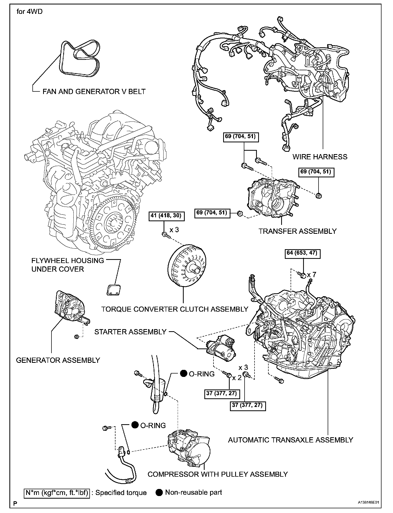
b. 4WD: Install the automatic transaxle.
26. INSTALL TRANSFER ASSEMBLY (for 4WD)
27. INSTALL STARTER ASSEMBLY