Part 2
ENGINE ASSEMBLYCOMPONENTS:
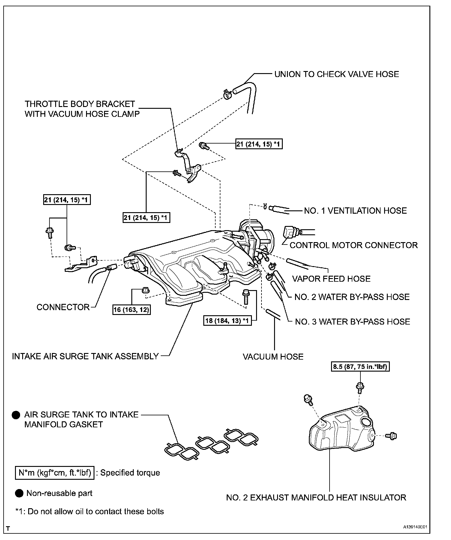
COMPONENTS:
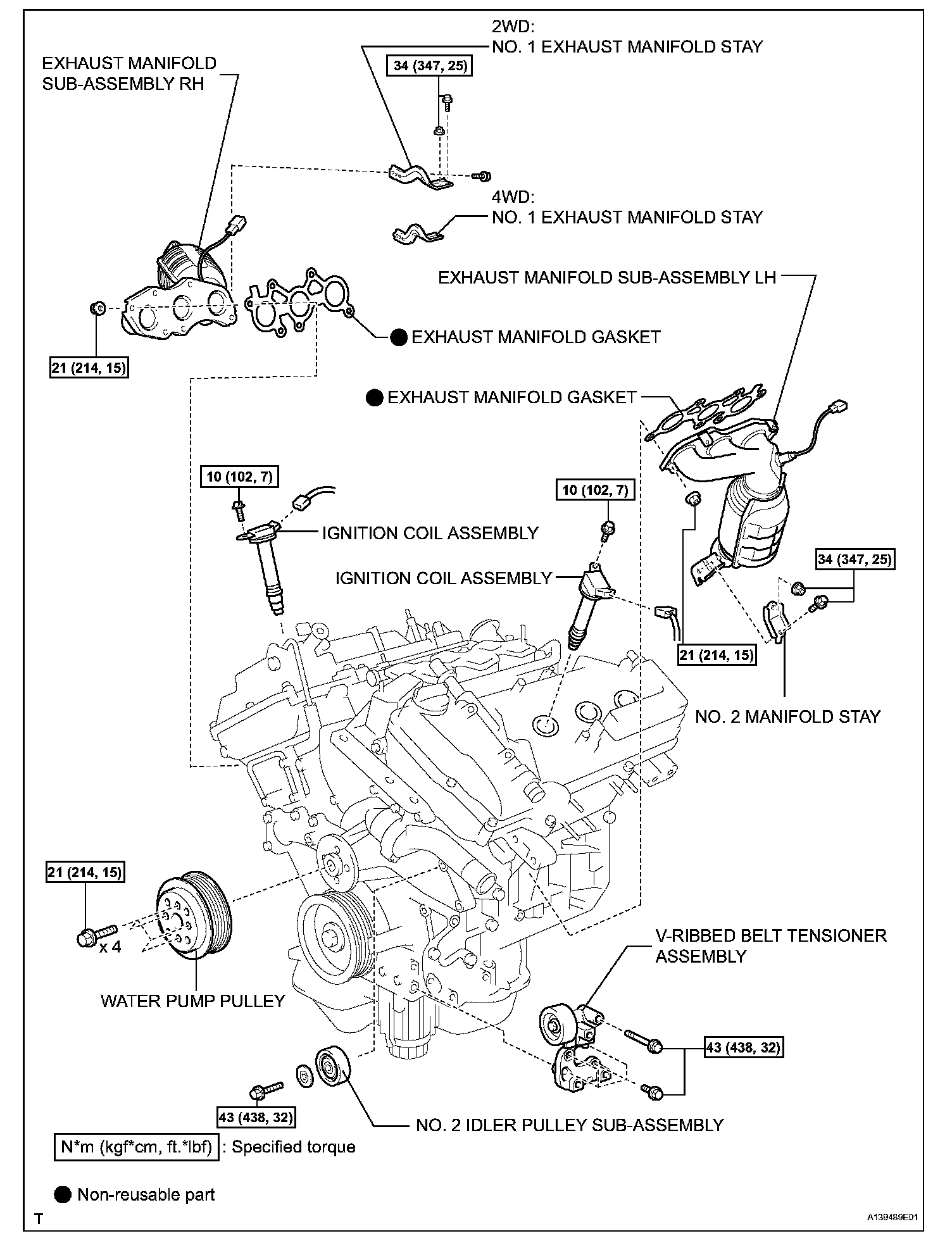
COMPONENTS:
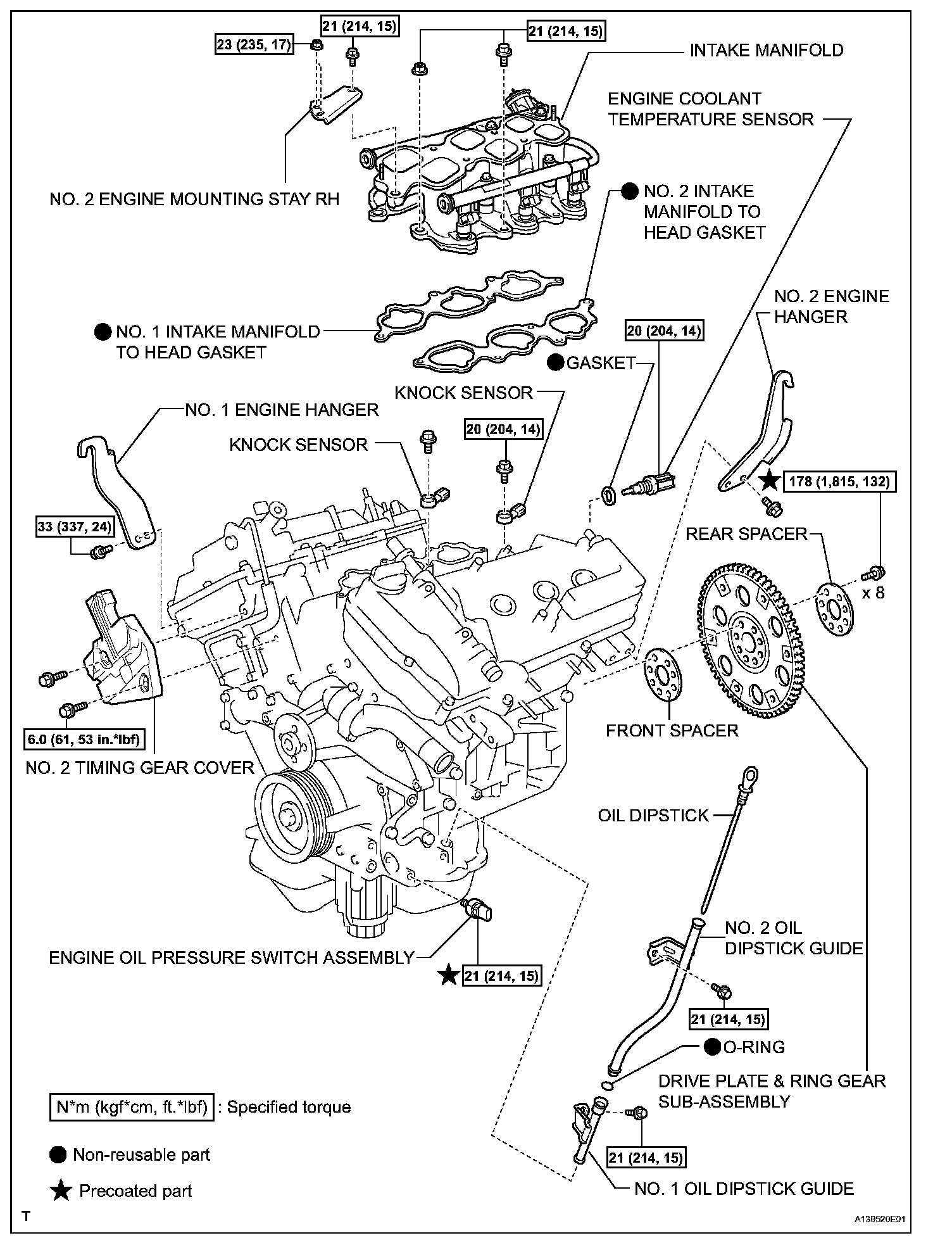
COMPONENTS:
COMPONENTS:
COMPONENTS:
COMPONENTS:
COMPONENTS:
COMPONENTS:
COMPONENTS:
COMPONENTS:
INSTALLATION (STEPS 28-54)
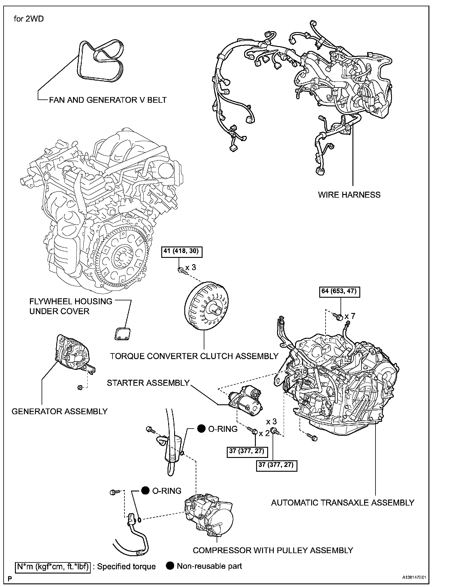
28. INSTALL ENGINE WIRE
a. Install the engine wire to the engine.
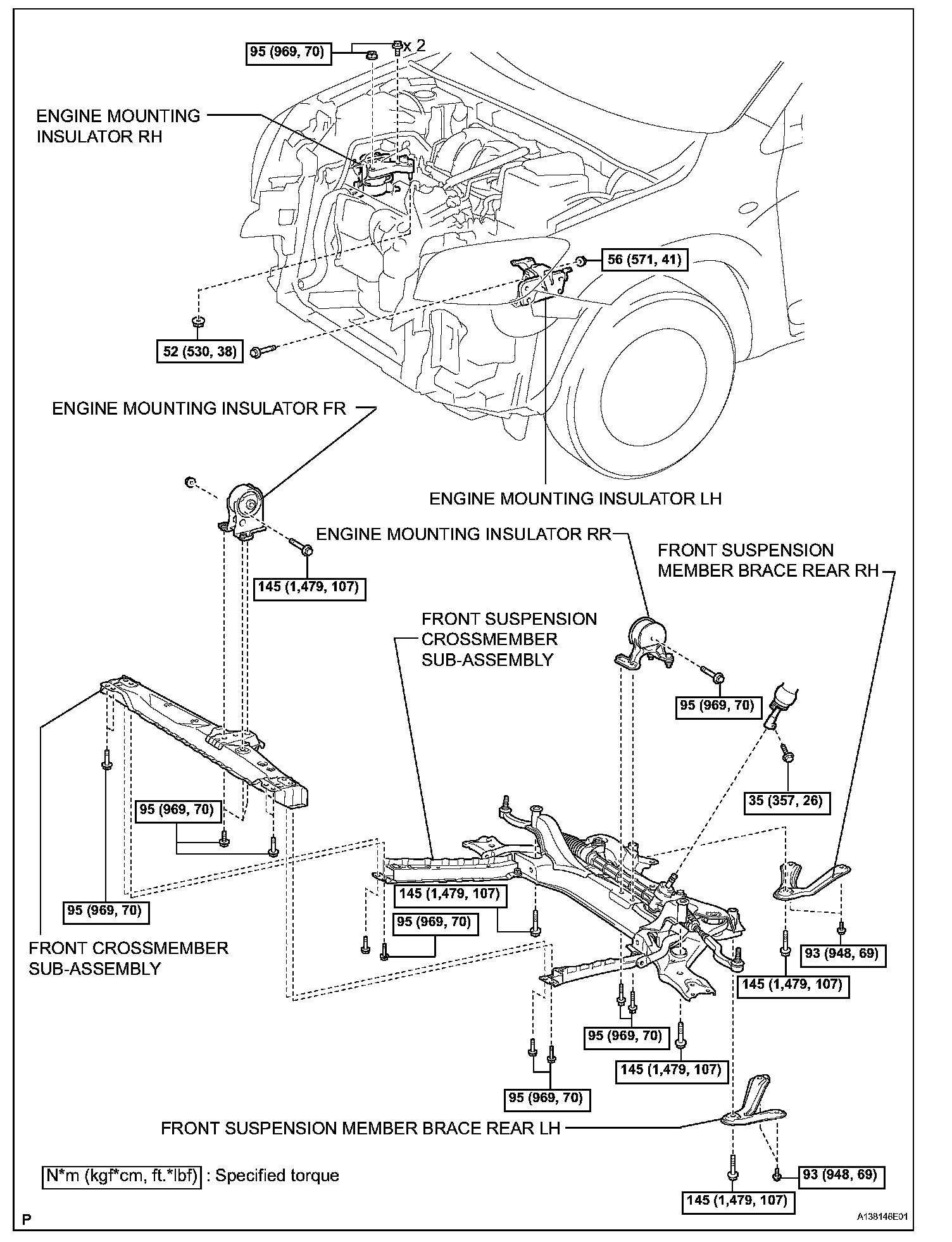
29. INSTALL FRONT SUSPENSION CROSSMEMBER SUB-ASSEMBLY
a. Attach the engine together with the transaxle to the suspension crossmember and mounting.
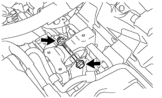
b. Install the bolt which secures the engine mounting bracket to the mounting insulator.
Torque: 95 Nm (969 kgf-cm, 70 ft. lbs.)
30. INSTALL FRONT CROSSMEMBER SUB-ASSEMBLY
a. Install the bolt and nut which secures the engine mounting bracket to the mounting insulator.
Torque: 145 Nm (1,479 kgf-cm, 107 ft. lbs.)
31. INSTALL ENGINE WITH TRANSAXLE
a. Place the engine on an engine lifter.
HINT: Place the engine on wooden blocks or an equivalent so that the engine is level.
b. Using the chain block, slowly install the engine to the vehicle and the intermediate shaft to the pinion.
CAUTION: Do not raise the engine more than necessary. If the engine is raised excessively, the vehicle may also be lifted up.
NOTICE:
^ Make sure that the engine is clear of all wiring and hoses.
^ While raising the engine into the vehicle, do not allow it to contact the vehicle.
^ Align the matchmarks on the intermediate shaft and pinion.
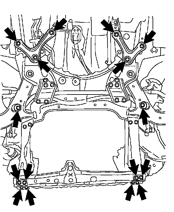
c. Temporarily install the suspension member and crossmember with the 10 bolts.
d. Temporarily install the member brace rear RH and LH with the 6 bolts.
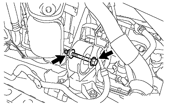
e. Install the engine mounting insulator LH with the bolt and nut.
Torque: 56 Nm (571 kgf-cm, 41 ft. lbs.)
NOTICE: While holding the bolt in place, tighten the nut.
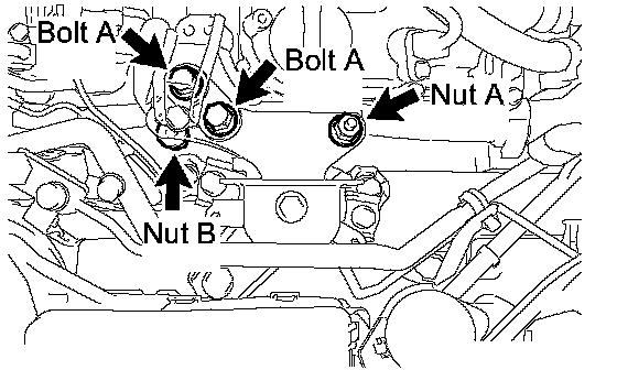
f. Install the engine mounting insulator RH with the 2 bolts and 2 nuts.
Torque:
95 Nm (969 kgf-cm, 70 ft. lbs.) for bolt and nut A
52 Nm (530 kgf-cm, 38 ft. lbs.) for nut B
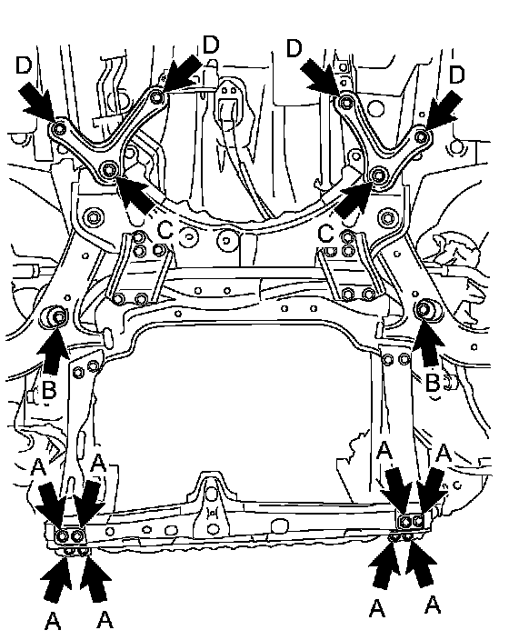
g. Tighten the suspension member and crossmember's bolts.
Torque:
96 Nm (979 kgf-cm, 71 ft. lbs.) for bolt A
145 Nm (1,478 kgf-cm, 107 ft. lbs.) for bolt B
h. Tighten the member brace rear's bolts.
Torque:
145 Nm (1,478 kgf-cm, 107 ft. lbs.) for bolt C
93 Nm (948 kgf-cm, 69 ft. lbs.) for bolt D
i. Remove the sling device and chain block.
j. Remove the 2 bolts and No. 1 and No. 2 engine hangers.
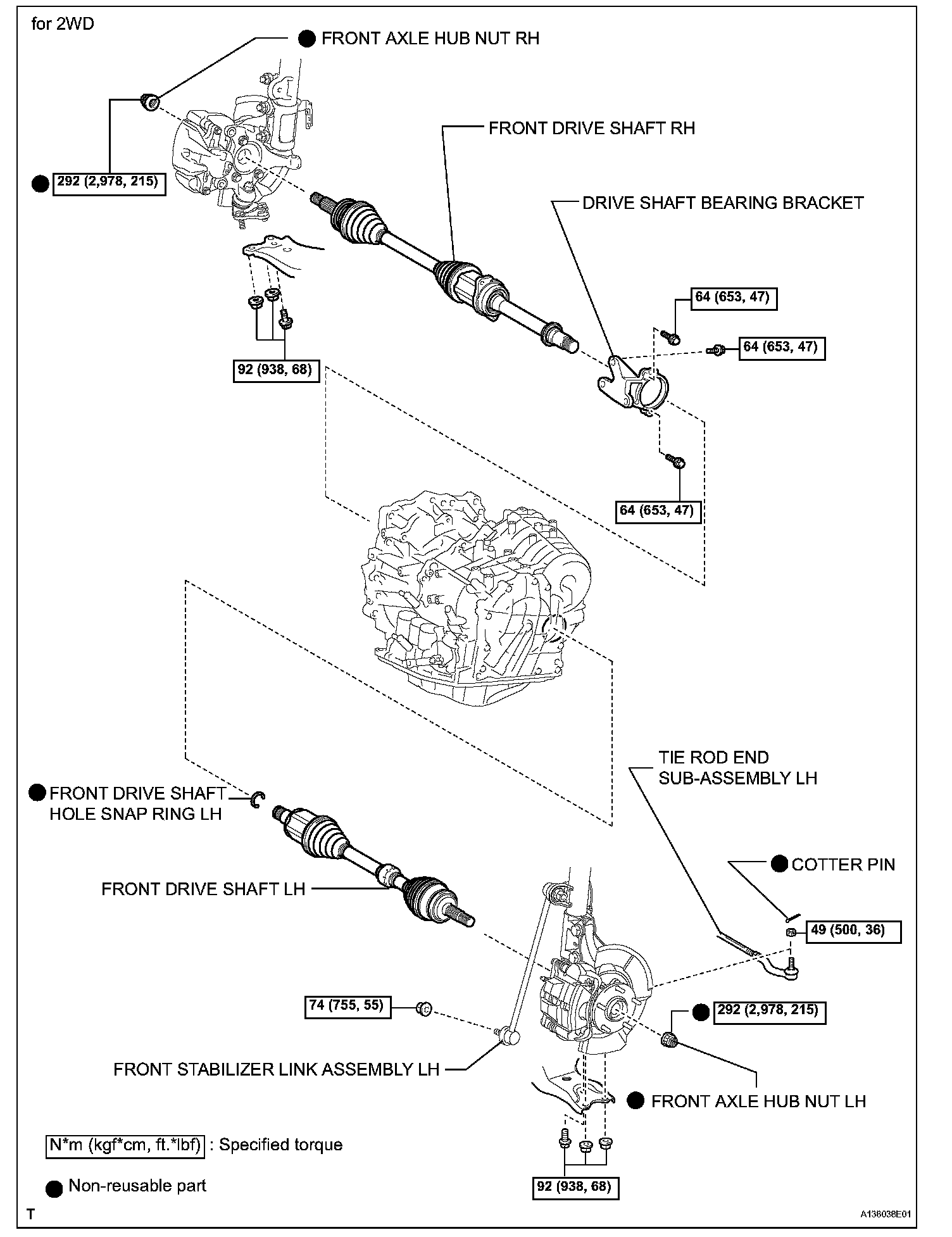
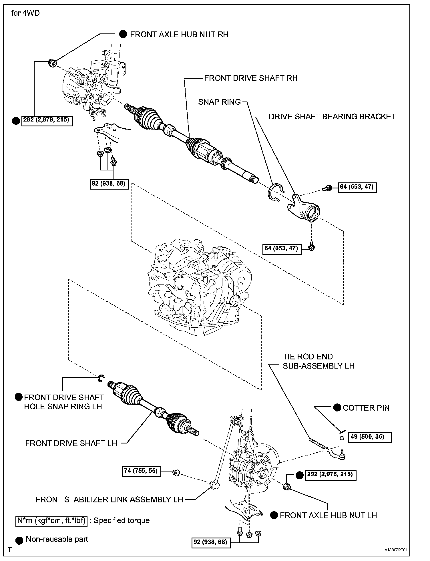
32. INSTALL FRONT DRIVE SHAFT LH
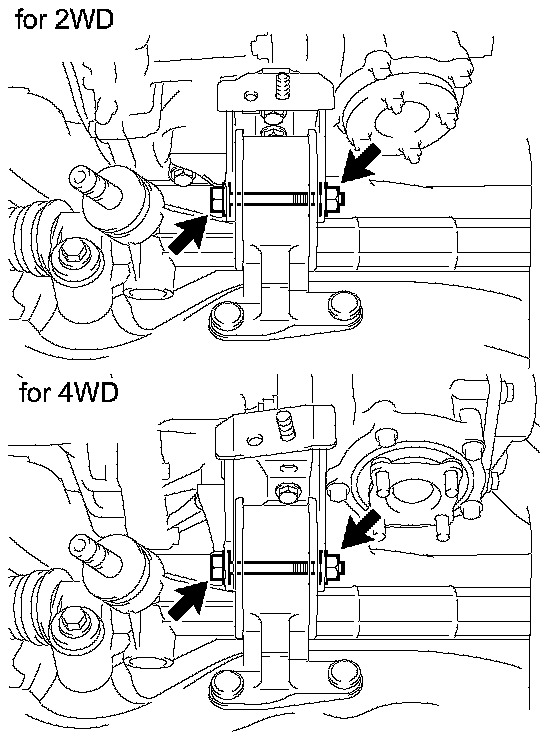
a. 2WD: Install the drive shaft.
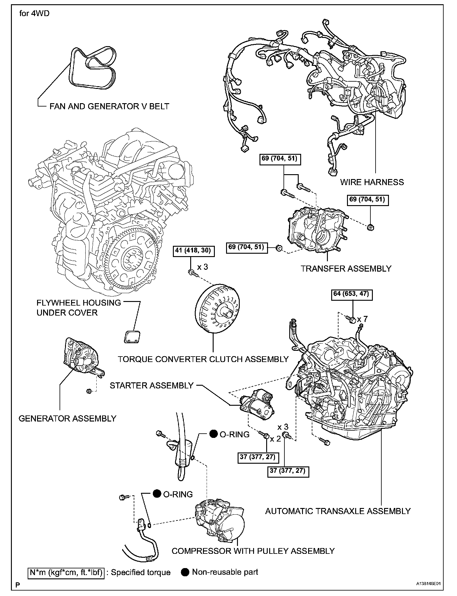
b. 4WD: Install the drive shaft.
33. INSTALL FRONT DRIVE SHAFT RH
a. 2WD: Install the drive shaft.
b. 4WD: Install the drive shaft.
34. CONNECT TIE ROD END SUB-ASSEMBLY LH
35. CONNECT TIE ROD END SUB-ASSEMBLY RH
36. CONNECT STEERING INTERMEDIATE SHAFT
37. CONNECT FRONT STABILIZER LINK ASSEMBLY LH
38. CONNECT FRONT STABILIZER LINK ASSEMBLY RH
39. INSTALL FRONT AXLE HUB NUT LH
a. Install the hub nut.
40. INSTALL FRONT AXLE HUB NUT RH
a. Install the hub nut.
41. INSTALL FRONT WHEELS
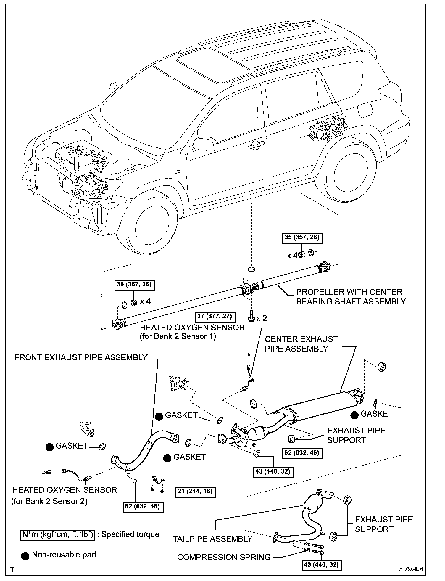
42. INSTALL PROPELLER WITH CENTER BEARING SHAFT ASSEMBLY
43. INSTALL CENTER EXHAUST PIPE ASSEMBLY
44. INSTALL FRONT EXHAUST PIPE ASSEMBLY
45. CONNECT TRANSMISSION CONTROL CABLE ASSEMBLY
a. 2WD: Connect the control cable.
b. 4WD: Connect the control cable.
46. CONNECT RADIATOR HOSE INLET
47. CONNECT RADIATOR HOSE OUTLET
48. CONNECT OIL COOLER HOSE
49. CONNECT SUCTION HOSE SUB-ASSEMBLY
50. INSTALL DISCHARGE HOSE SUB-ASSEMBLY
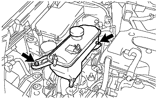
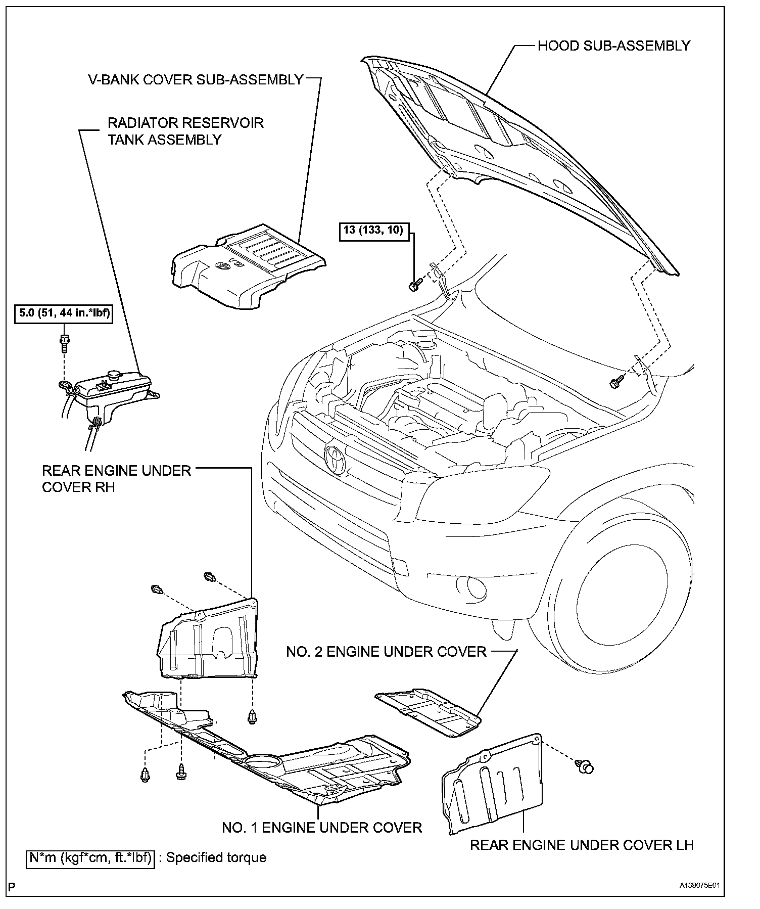
51. INSTALL RADIATOR RESERVOIR TANK ASSEMBLY
a. Install the reservoir tank with the 2 bolts.
Torque: 5.0 Nm (51 kgf-cm, 44 inch lbs.)
b. Connect the 2 hoses
52. INSTALL ECM
53. CONNECT HOSES AND CONNECTORS
a. Connect the 2 ECM connectors.
b. Connect the 2 heater hoses.
c. Connect the fuel hoses.
d. Connect the starter wire with the nut.
Torque: 9.8 Nm (100 kgf-cm, 7 ft. lbs.)
e. Connect the 3 connectors and wire with the nut.
Torque: 12 Nm (122 kgf-cm, 8.85 ft. lbs.)
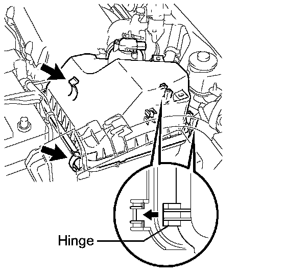
f. Install the engine room junction block cover (upper).
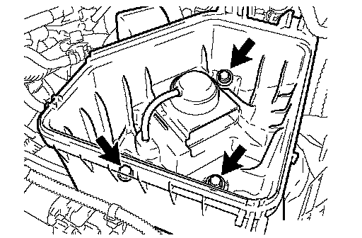
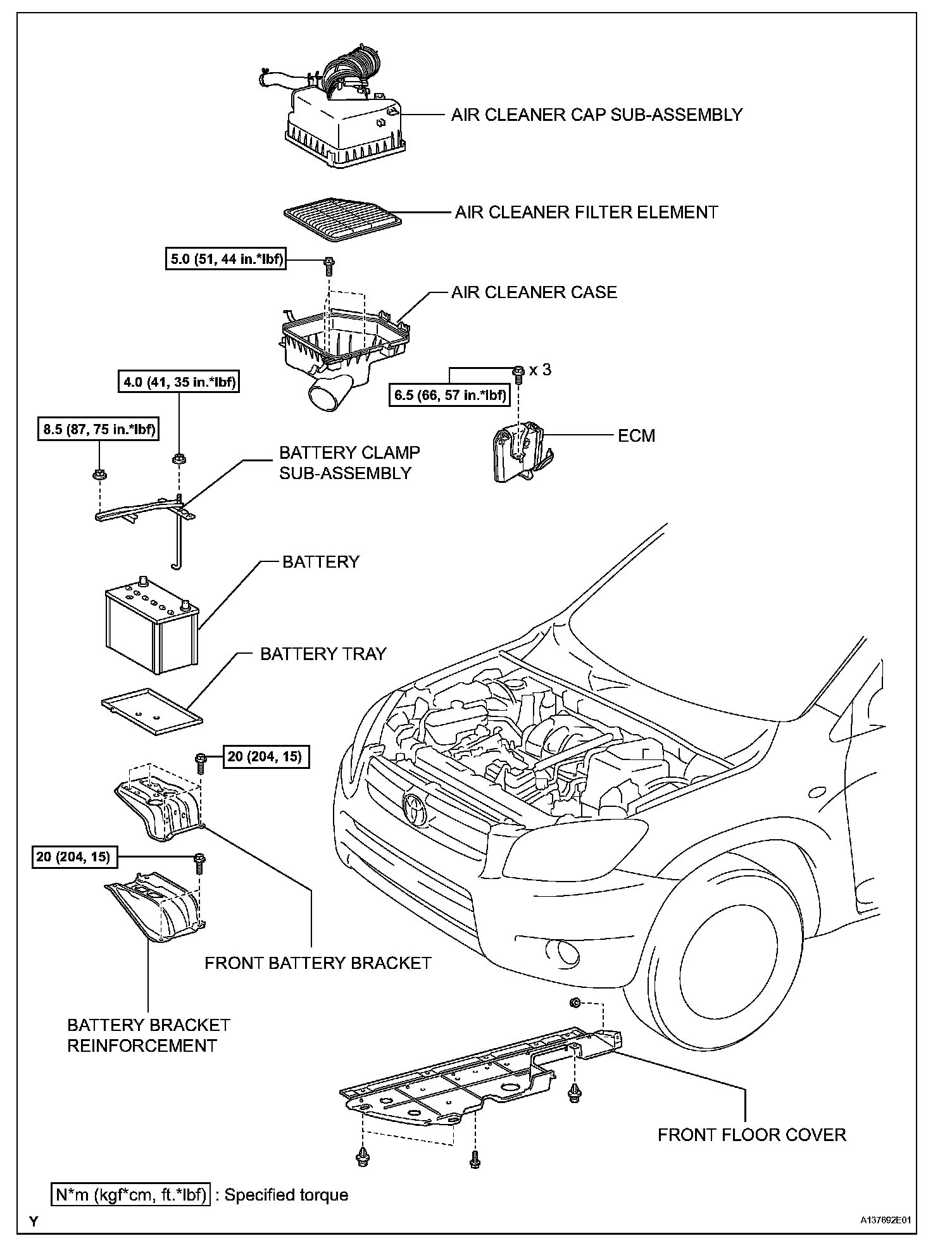
54. INSTALL AIR CLEANER CASE
a. Install the air cleaner case with the 3 bolts.
Torque: 5.0 Nm (51 kgf-cm, 44 inch lbs.)
b. Connect the harness clamp.