Part 2
ENGINE UNITCOMPONENTS:

COMPONENTS:

COMPONENTS:

COMPONENTS:

COMPONENTS:

COMPONENTS:

COMPONENTS:

COMPONENTS:

COMPONENTS:

REASSEMBLY (STEPS 19-36)
19. INSTALL CYLINDER HEAD SUB-ASSEMBLY (for Bank 2)
a. Check the piston protrusions for each cylinder.
(1) Clean the cylinder block with solvent.
(2) Set the piston of the cylinder to be measured to slightly before TDC.
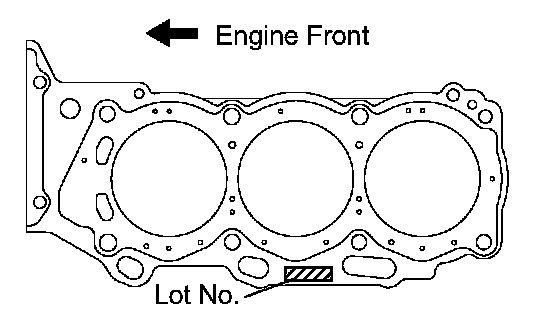
b. Place the cylinder head gasket on the cylinder block surface with the front face of the Lot No. stamp upward.
NOTICE:
^ Be careful of the installation direction.
^ Gently place the cylinder head in order not to damage the gasket with the bottom part of the head.
c. Place the cylinder head on the cylinder block.
NOTICE: Ensure that no oil is on the mounting surface of the cylinder head.
HINT: The cylinder head bolts are tightened in 3 progressive steps.
d. Apply a light coat of engine oil to the threads and under the heads of the cylinder head bolts.

e. Step 1
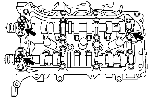
(1) Using a 10 mm bi-hexagon wrench, install and uniformly tighten the 8 cylinder head bolts with the plate washers in several steps, in the sequence shown in the illustration.
Torque: 36 Nm (367 kgf-cm, 27 ft. lbs.)
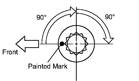
f. Step 2
(1) Mark the cylinder head bolt heads with paint as shown in the illustration.
(2) Tighten the cylinder head bolts another 90° in the sequence shown in step 1.
g. Step 3
(1) Tighten the cylinder head bolts by an additional 90° in the sequence shown in step 1.
(2) Check that the painted mark is now facing rearward.

h. Install the 2 bolts in the order shown in the illustration.
Torque: 30 Nm (306 kgf-cm, 22 ft. lbs.)
20. INSTALL VALVE LASH ADJUSTER ASSEMBLY
a. Be sure to inspect the valve lash adjuster before installing it.
b. Install the lash adjusters.
NOTICE: Install the lash adjuster at the same place it was removed from.
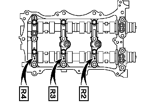
21. INSTALL NO. 1 VALVE ROCKER ARM SUBASSEMBLY
a. Apply engine oil to the lash adjuster tips and valve stem cap ends.
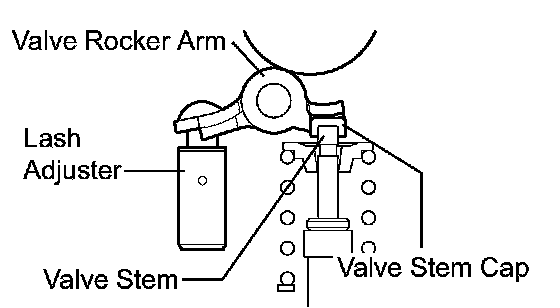
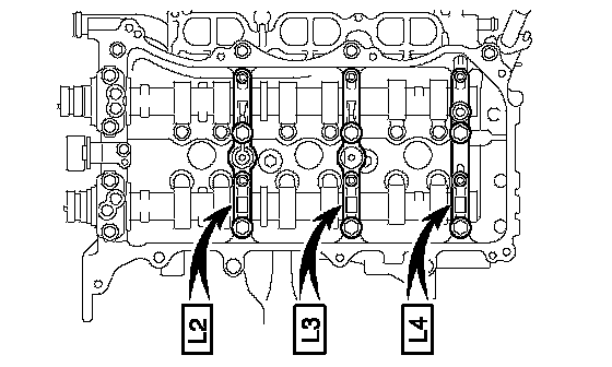
b. Make sure that the valve rocker arms are installed as shown in the illustration.
22. INSTALL CAMSHAFT BEARING CAP (for Bank 1)
a. Apply engine oil to the camshaft journals, camshaft housings and bearing caps.
b. Install the No. 1 camshaft and No. 2 camshaft to the camshaft housing.
c. Confirm the marks and numbers on the camshaft bearing caps and place them each in their proper position and direction.

d. Temporarily install the 8 bolts in the order shown in the illustration.
Torque: 10 Nm (102 kgf-cm, 7 ft. lbs.)
23. INSTALL CAMSHAFT HOUSING SUB-ASSEMBLY (for Bank 1)
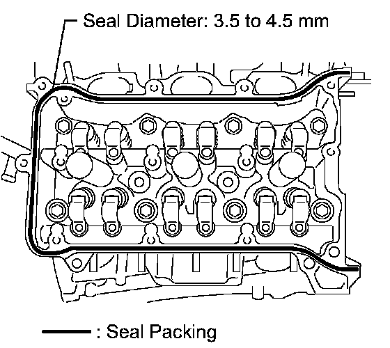
a. Apply seal packing in a continuous line as shown in the illustration.
Seal packing: Toyota Genuine Seal Packing Block, Three Bond 1207B or Equivalent
Standard seal diameter: 3.5 to 4.5 mm (0.138 to 0.177 inch)
NOTICE:
^ Remove any oil from the contact surface.
^ Install the camshaft housing within 3 minutes and tighten the bolts within 15 minutes after applying seal packing.
^ Do not start the engine for at least 2 hours after the installation.

b. Install the camshaft housing, and install the 12 bolts in the order shown in the illustration.
Torque: 28 Nm (286 kgf-cm, 21 ft. lbs.)
NOTICE: Make sure that the knock pin of the camshaft is positioned as shown in the illustration before installing the camshaft housing.

c. Tighten the 8 bolts in the order shown in the illustration.
Torque: 16 Nm (163 kgf-cm, 12 ft. lbs.)
NOTICE: Thoroughly wipe clean any seal packing.
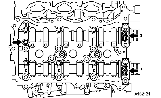
d. Install 3 new gaskets.
24. INSTALL CAMSHAFT BEARING CAP (for Bank 2)
a. Apply engine oil to the camshaft journals, camshaft housings and bearing caps.
b. Install the camshaft No. 3 and camshaft No. 4 to the camshaft housing.
c. Confirm the marks and numbers on the camshaft bearing caps and place them each in their proper position and direction.

d. Temporarily install the 8 bolts in the order shown in the illustration.
Torque: 10 Nm (102 kgf-cm, 7 ft. lbs.)
25. INSTALL CAMSHAFT HOUSING SUB-ASSEMBLY (for Bank 2)
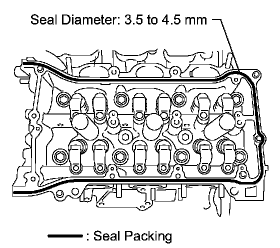
a. Apply seal packing in a continuous line as shown in the illustration.
Seal packing: Toyota Genuine Seal Packing Block, Three Bond 1207B or Equivalent
Standard seal diameter: 3.5 to 4.5 mm (0.138 to 0.177 inch)
NOTICE:
^ Remove any oil from the contact surface.
^ Install the camshaft housing within 3 minutes and tighten the bolts within 15 minutes after applying seal packing.
^ Do not start the engine for at least 2 hours after the installation.

b. Install the camshaft housing and tighten the 13 bolts in the order shown in the illustration.
Torque: 28 Nm (286 kgf-cm, 21 ft. lbs.)
NOTICE: Make sure that the knock pin of the camshaft is positioned as shown in the illustration before installing the camshaft housing.

c. Tighten the 8 bolts in the order shown in the illustration.
Torque: 16 Nm (163 kgf-cm, 12 ft. lbs.)
NOTICE: Thoroughly wipe clean any seal packing.
d. Install 3 new gaskets.
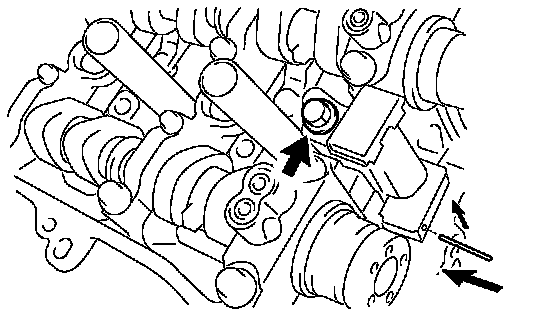
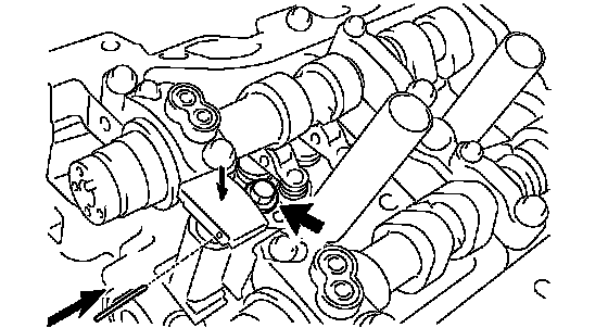
26. INSTALL NO. 2 CHAIN TENSIONER ASSEMBLY
a. Install the chain tensioner with the bolt.
Torque: 21 Nm (214 kgf-cm, 15 ft. lbs.)
b. While pushing in the tensioner, insert a pin of 1.0 mm (0.039 inch) into the hole to fix it in place.
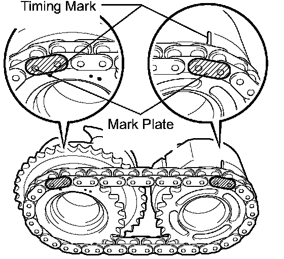
27. INSTALL CAMSHAFT TIMING GEARS AND NO. 2 CHAIN (for Bank 1)
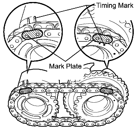
a. Align the mark plate (yellow) with the timing marks (1 dot mark) of the camshaft timing gears as shown in the illustration.
b. Apply a small amount of engine oil to the bolt threads and bolt-seating surface.
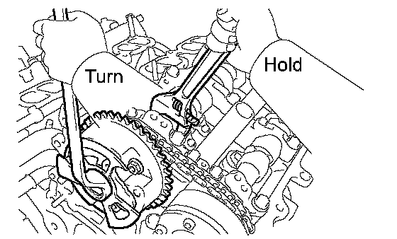
c. Align the knock pin of the camshaft with the pin hole of the camshaft timing gear. Install the camshaft timing gear and camshaft timing exhaust gear with the No. 2 chain installed.
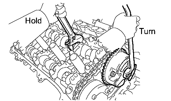
d. Hold the hexagonal portion of the camshaft with a wrench, and tighten the 2 bolts.
Torque: 100 Nm (1,020 kgf-cm, 74 ft. lbs.)
e. Remove the pin from the No. 2 chain tensioner.
28. INSTALL NO. 3 CHAIN TENSIONER ASSEMBLY
a. Install the chain tensioner with the bolt.
Torque: 21 Nm (214 kgf-cm, 15 ft. lbs.)
b. While pushing in the tensioner, insert a pin of 1.0 mm (0.039 inch) into the hole to fix it in place.
29. INSTALL CAMSHAFT TIMING GEARS AND NO. 2 CHAIN (for Bank 2)
a. Align the mark plate (yellow) with the timing marks (2 dot mark) of the camshaft timing gears as shown in the illustration.
b. Apply a small amount of engine oil to the bolt threads and bolt-seating surface.
c. Align the knock pin of the camshaft with the pin hole of the camshaft timing gear. Install the camshaft timing gear and camshaft timing exhaust gear with the No. 2 chain installed.
d. Hold the hexagonal portion of the camshaft with a wrench, and tighten the 2 bolts.
Torque: 100 Nm (1,020 kgf-cm, 74 ft. lbs.)
e. Remove the pin from the No. 2 chain tensioner.
30. INSTALL CRANKSHAFT TIMING GEAR OR SPROCKET
a. Install the timing gear set keys and timing gear as shown in the illustration.
31. INSTALL NO. 1 CHAIN VIBRATION DAMPER
a. Install the chain vibration damper with the 2 bolts.
Torque: 23 Nm (235 kgf-cm, 17 ft. lbs.)
32. INSTALL NO. 2 CHAIN VIBRATION DAMPER
a. Install the 2 chain vibration damper.
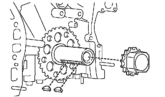
33. INSTALL IDLE SPROCKET ASSEMBLY
a. Apply a light coat of engine oil to the rotating surface of the No. 1 idle gear shaft.
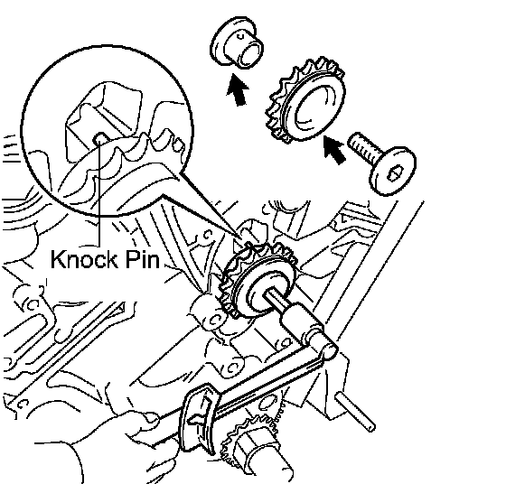
b. Temporarily install the No. 1 idle gear shaft and idle sprocket with the No. 2 idle gear shaft while aligning the knock pin of the No. 1 idle gear shaft with the knock pin groove of the cylinder block.
NOTICE: Be careful of the idle gear direction.
c. Using a 10 mm hexagon wrench, tighten the No. 2 idle gear shaft.
Torque: 60 Nm (612 kgf-cm, 44 ft. lbs.)
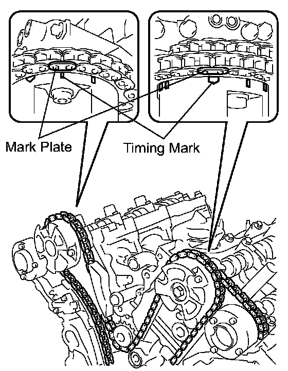
34. INSTALL CHAIN SUB-ASSEMBLY
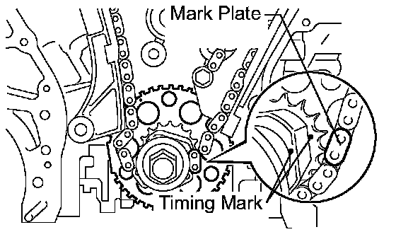
a. Align the mark plate and timing mark as shown in the illustration and install the chain.
NOTICE: Do not pass the chain over the crankshaft, just put it on it.
HINT: The chain mark plate is orange.
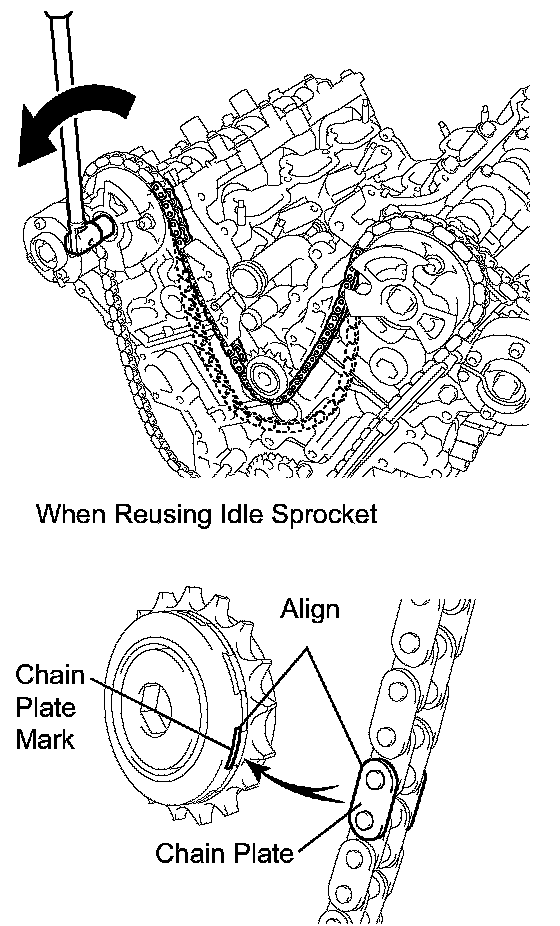
b. Turn the camshaft timing gear on the bank 1 counterclockwise to tighten the chain between the banks.
NOTICE: If reusing the idle sprocket, align one of the idle sprocket's chain plate marks with one of the chain's chain plates when installing the idle sprocket.
c. Align the mark plate and timing mark as shown in the illustration and install the chain onto the crankshaft timing gear.
HINT: The chain mark plate is yellow.
d. Temporarily tighten the pulley set bolt.
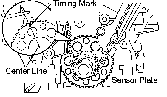
e. Turn the crankshaft clockwise to set it to the bank 1 block bore center line (TDC/compression).
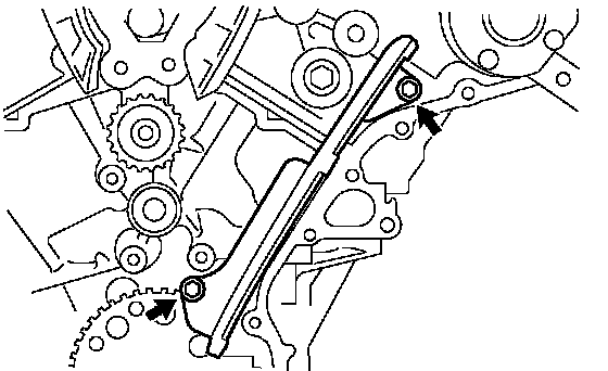
35. INSTALL CHAIN TENSIONER SLIPPER
a. Install the chain tensioner slipper.
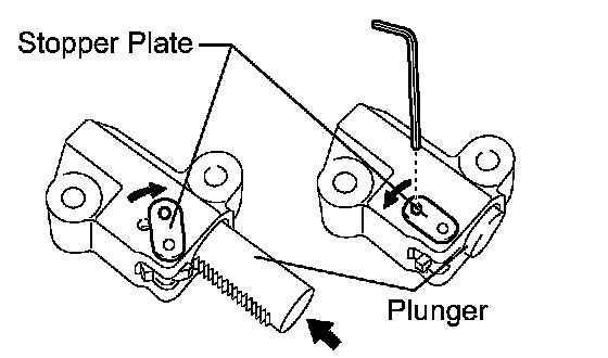
36. INSTALL NO. 1 CHAIN TENSIONER ASSEMBLY
a. Move the stopper plate upward to release the lock, and push the plunger deep into the tensioner.
b. Move the stopper plate downward to set the lock, and insert a hexagon wrench into the hole of the stopper plate.
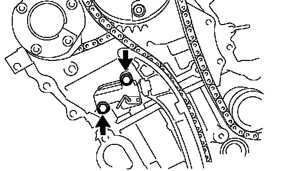
c. Install the chain tensioner with the 2 bolts.
Torque: 10 Nm (102 kgf-cm, 7 ft. lbs.)

d. Remove the lock pin of the chain tensioner. Check that each timing mark is aligned with the crankshaft at the TDC/compression.
e. Remove the pulley set bolt.