Part 1
AUTOMATIC TRANSAXLE UNITREASSEMBLY
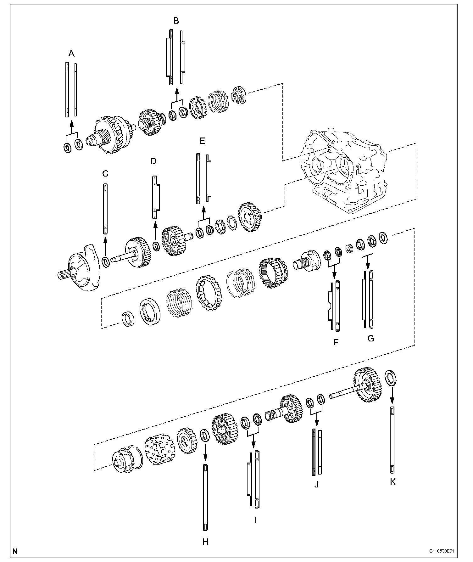
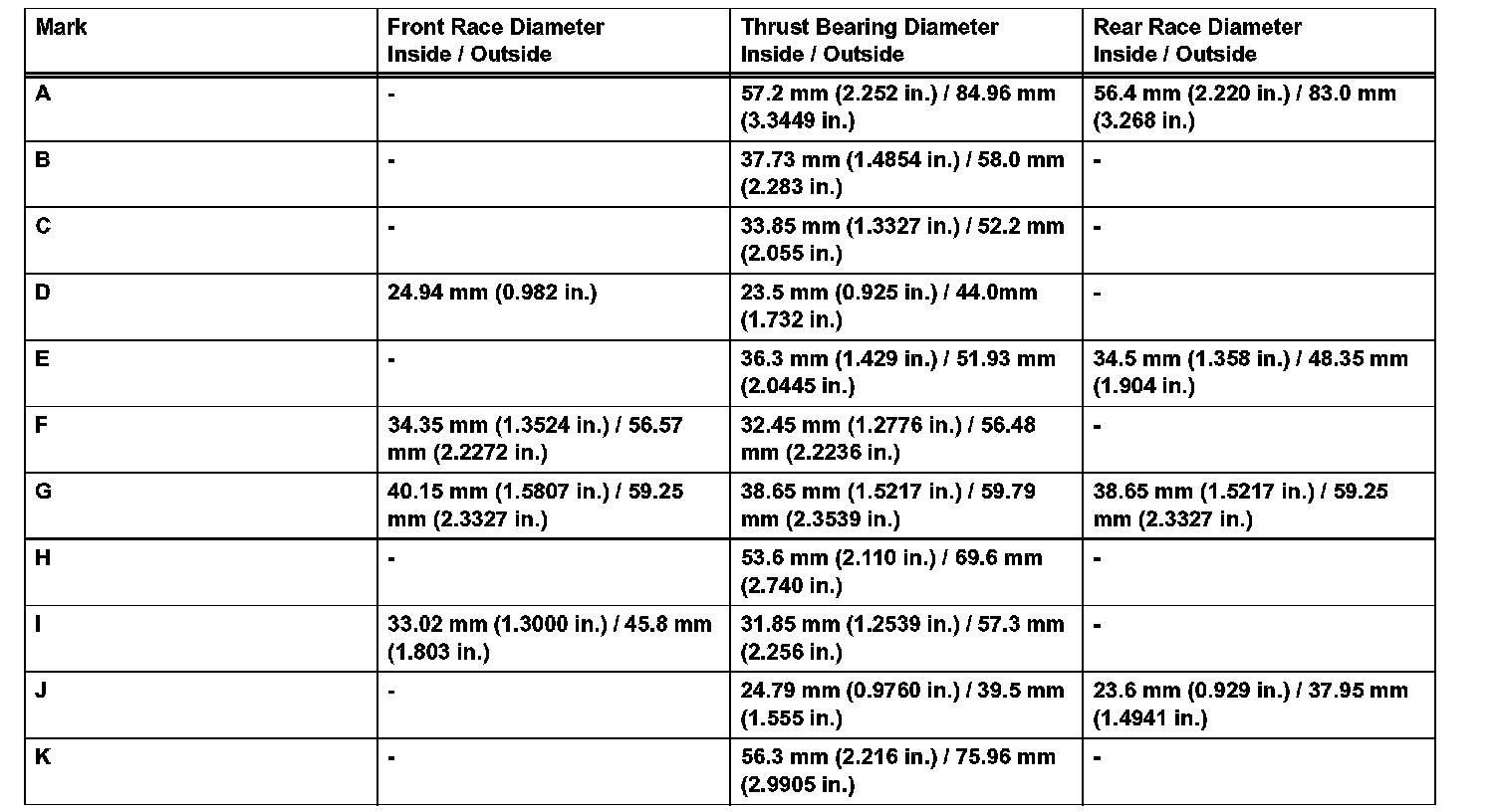
Standard bearing position:
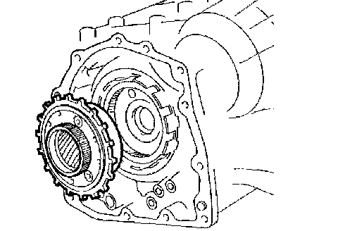
1. BEARING POSITION
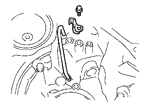
2. INSTALL DIFFERENTIAL GEAR LUBE APPLY TUBE
a. Install the differential gear lube apply tube and transaxle apply tube clamp to the transaxle housing with the bolt.
Torque: 9.8 Nm (100 kgf-cm, 87 inch lbs.)
NOTICE: Make sure to insert the pipe to the stopper.
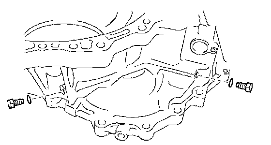
3. INSTALL NO. 1 TRANSAXLE CASE PLUG
a. Install 2 new O-rings to the 2 plugs.
b. Install the 2 plugs to the transaxle rear cover.
Torque: 7.4 Nm (75 kgf-cm, 65 inch lbs.)
4. INSTALL UNDERDRIVE OUTPUT SHAFT OIL SEAL RING
a. Coat a new oil seal ring with ATF and install it to the transaxle housing.
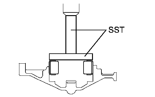
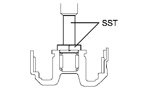
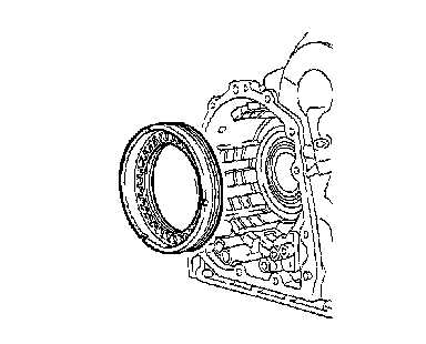
5. INSTALL UNDERDRIVE CYLINDRICAL ROLLER BEARING
a. Coat the underdrive cylindrical roller bearing with ATF.
b. Using SST and a press, press in the underdrive cylindrical roller bearing.
SST 09950-60020 (09951-00810), 09950-70010 (09951-07100)
NOTICE: Do not apply excessive pressure to the bearing.
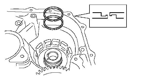
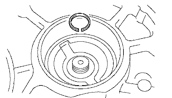
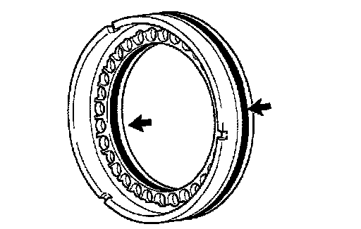
6. INSTALL UNDERDRIVE CLUTCH DRUM OIL SEAL RING
a. Coat 2 new oil seal rings with ATF, and install them to the transaxle rear cover.
NOTICE:
^ Do not expand the end gap of the oil seal ring too much.
^ Fix the hooks firmly. Confirm that the oil seal ring rotates freely in its groove.
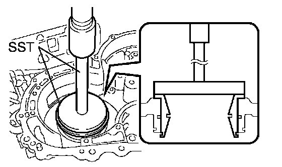
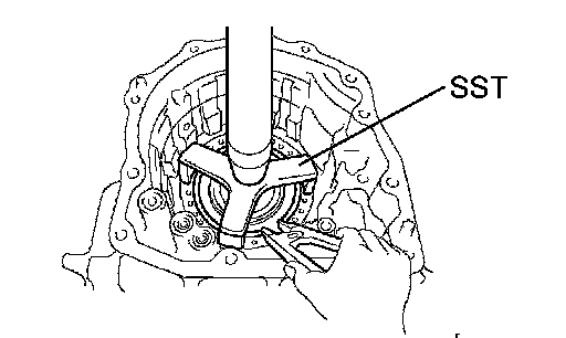
7. INSTALL NEEDLE ROLLER BEARING
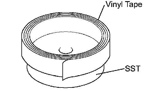
a. Wrap vinyl tape around SST 4.0 mm (0.157 inch) from the bottom of SST until the thickness of the tape is about 5.0 mm (0.197 inch).
SST 09950-60010 (09951-00320), 09950-70010 (09951-07100)
NOTICE: Clean SST to remove deposited oil before wrapping vinyl tape.
b. Coat the needle roller bearing with ATF.
c. Using SST and a press, press in the needle-roller bearing to the transaxle case.
SST 09950-60010 (09951-00320), 09950-70010 (09951-07100)
NOTICE: When the wrapped vinyl tape contacts the transaxle case, stop press-fitting.
8. INSTALL UNDERDRIVE BRAKE PISTON
a. Coat 2 new O-rings with ATF, and install them to the underdrive brake piston.
NOTICE:
^ Make sure that the O-rings are not twisted or pinched when they are installed.
^ Apply sufficient ATF to the O-ring before installing.
b. Coat the underdrive brake piston with ATF.
c. Install the underdrive brake piston to the transaxle case.
NOTICE: Be careful not to damage the O-ring.
9. INSTALL UNDERDRIVE BRAKE RETURN SPRING SUB-ASSEMBLY
a. Place SST on the return spring and compress the return spring with a press.
NOTICE:
^ Stop the press when the spring seat is lowered to a position 1 to 2 mm (0.039 to 0.078 inch) from the snap ring groove to prevent the spring seat from being deformed.
^ After installing the return spring, check that all the return spring's springs fit in the piston correctly.
SST 09387-00020
b. Using a snap ring expander, press in the snap ring to the transaxle case.
NOTICE: The snap ring must be fully engaged in the groove of the transaxle case.
10. INSTALL NO. 2 BREATHER PLUG
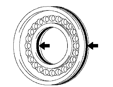
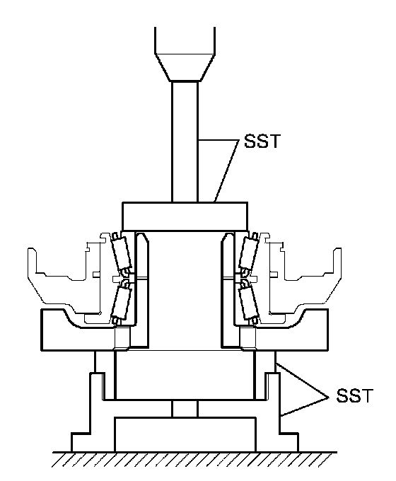
11. INSTALL COUNTER DRIVE GEAR BEARING
a. Coat the counter drive gear bearing with ATF.
b. Using SST and a press, press in the bearing outer race.
SST 09950-60020 (09951-01030), 09950-70010 (09951-07150), 09649-17010
NOTICE:
^ Do not apply excessive pressure to the bearing.
^ Press-fit the bearing outer race until it contacts the transaxle case.
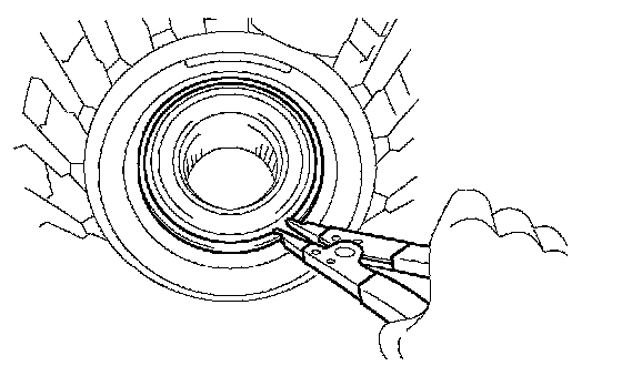
c. Using a snap ring expander, install the snap ring.
NOTICE: The white mark side of the snap ring should face upward.
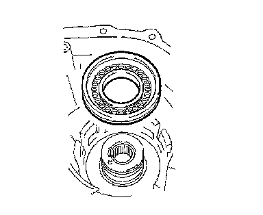
12. INSTALL COUNTER DRIVE GEAR
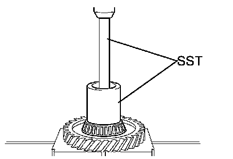
a. Coat the counter drive gear with ATF.
b. Using SST and a press, press in the tapered roller bearing to the counter drive gear.
SST 09950-70010 (09951-07150), 09649-17010
NOTICE: Do not apply excessive pressure to the bearing.
c. Using SST and a press, press in the counter drive gear and bearing to the transaxle case.
SST 09950-70010 (09951-07150), 09223-15030, 09527-17011, 09950-60020 (09951-00750)
NOTICE: Do not apply excessive pressure to the counter drive gear.
13. INSTALL 1ST AND REVERSE BRAKE PISTON
a. Coat 2 new O-rings with ATF.
b. Install the 2 O-rings to the 1st and reverse brake piston.
NOTICE:
^ Make sure that the O-rings are not twisted or pinched when they are installed.
^ Apply sufficient ATF to the O-ring prior to assembling.
c. Coat the 1st and reverse brake piston with ATF, and install it to the transaxle case.
NOTICE: Be careful not to damage the O-ring.
14. INSTALL 1ST AND REVERSE BRAKE RETURN SPRING SUB-ASSEMBLY
a. Place SST on the return spring and compress the return spring with a press.
NOTICE:
^ Stop the press when the spring seat is lowered 1 to 2 mm (0.039 to 0.078 inch) from the snap ring groove to prevent the spring seat from being deformed.
^ After installing the return spring, check that all the return spring's springs fit in the piston correctly.
SST 09387-00070
b. Using a snap ring expander, press in the snap ring to the transaxle case.
NOTICE:
^ The snap ring must be fully engaged in the groove of the transaxle case.
^ Fix the snap ring to the inside of the claw of the spring seat firmly.
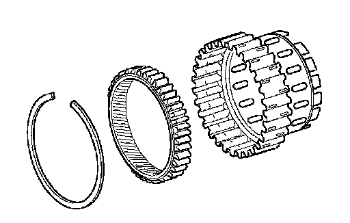
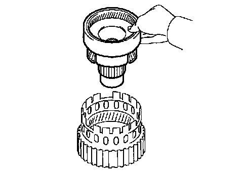
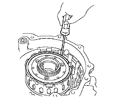
15. INSTALL FRONT PLANETARY RING GEAR
a. Using a screwdriver, install the front planetary ring gear and snap ring to the brake hub.
NOTICE: Confirm that the snap ring is engaged in the groove of the brake hub correctly.
16. INSTALL FRONT PLANETARY GEAR ASSEMBLY
a. Install the front planetary gear to the brake hub.
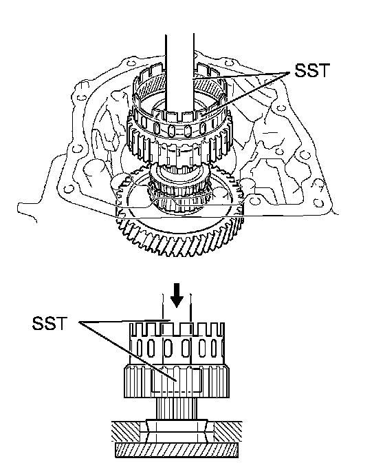
b. Using SST and a press, press-fit the front planetary gear.
SST 09950-60010 (09951-00500), 09950-70010 (09951-07100)
NOTICE:
^ Do not apply excessive pressure to the planetary gear.
^ Press the inner race of the LH tapered roller bearing, counter gear and front planetary gear to the position where no preload should be applied to one pair of tapered roller bearings (left and right).
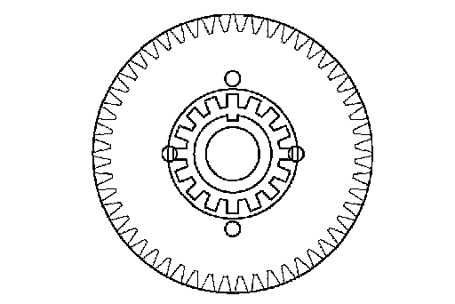
c. Install a new washer as shown in the illustration.
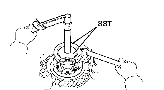
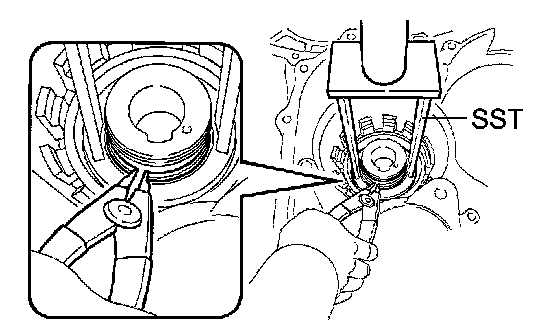
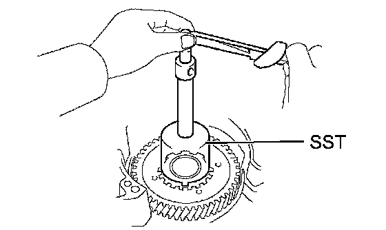
d. Using SST, install the nut.
SST 09387-00030, 09387-00080
Torque: 280 Nm (3,355 kgf-cm, 207 ft. lbs.)
NOTICE: Assemble the washer after pressing each part, then tighten the nut to the standard torque.
e. Using SST and a torque wrench, measure the turning torque of the bearing while rotating SST at 60 rpm. When the measured value is not as specified, gradually tighten the nut until it reaches the specified value.
SST 09387-00080
Standard turning torque at 60 rpm:
0.51 to 1.02 Nm (5.1 to 10.0 kgf-cm, 4.4 to 8.7 inch lbs.) for new bearing
0.26 to 0.51 Nm (2.7 to 5.2 kgf-cm, 2.3 to 4.5 inch lbs.) for used bearing
f. Tighten the nut gradually until the specified turning torque of the tapered roller bearing is measured.
Torque: 350 Nm (3,569 kgf-cm, 258 ft. lbs.)
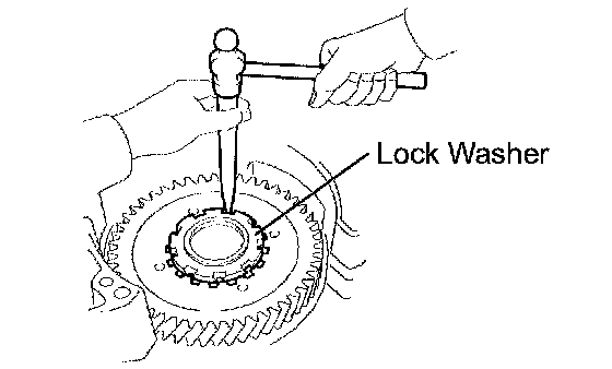
g. Using a chisel and hammer, stake the front lock washer.
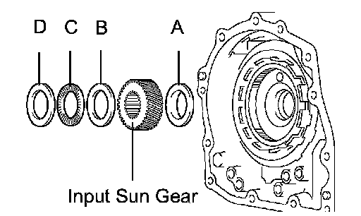
17. INSTALL INPUT SUN GEAR
a. Coat the 2 thrust bearings with ATF.
b. Install the 2 thrust bearings, bearing race and input sun gear to the front planetary gear.
NOTICE:
^ Install the bearing race on the side of the front planetary carrier. Be careful about the direction of the race.
^ When installing the thrust bearing and front sun gears, be careful about the direction of the parts.
^ When install the bearing race on the side of the front sun gear, be careful of the direction of the race.
^ Install the thrust bearing and the race after holding the parts on the input sun gear by applying grease. Make sure that the assembling order is correct.
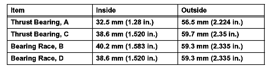
Standard thrust bearing and bearing race diameter:
18. INSTALL REAR PLANETARY GEAR ASSEMBLY
a. Install the rear planetary gear to the rear planetary ring gear.
b. Using a screwdriver, install the snap ring.
NOTICE: Confirm that the snap ring is fixed in the groove of the 1st and reverse brake hub correctly.
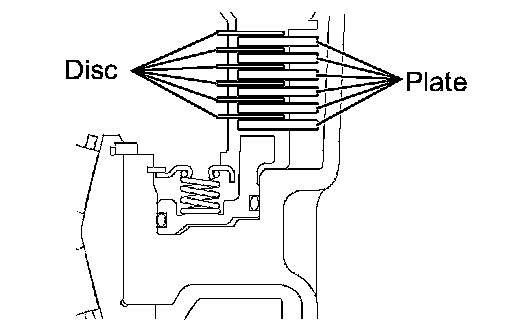
19. INSTALL 1ST AND REVERSE BRAKE CLUTCH DISC
a. Coat the 6 discs with the ATF.
b. Install the 6 plates and 6 discs.
NOTICE: Make sure that the plates and discs are installed as shown in the illustration.