Part 1
AUTOMATIC TRANSAXLE UNITREASSEMBLY
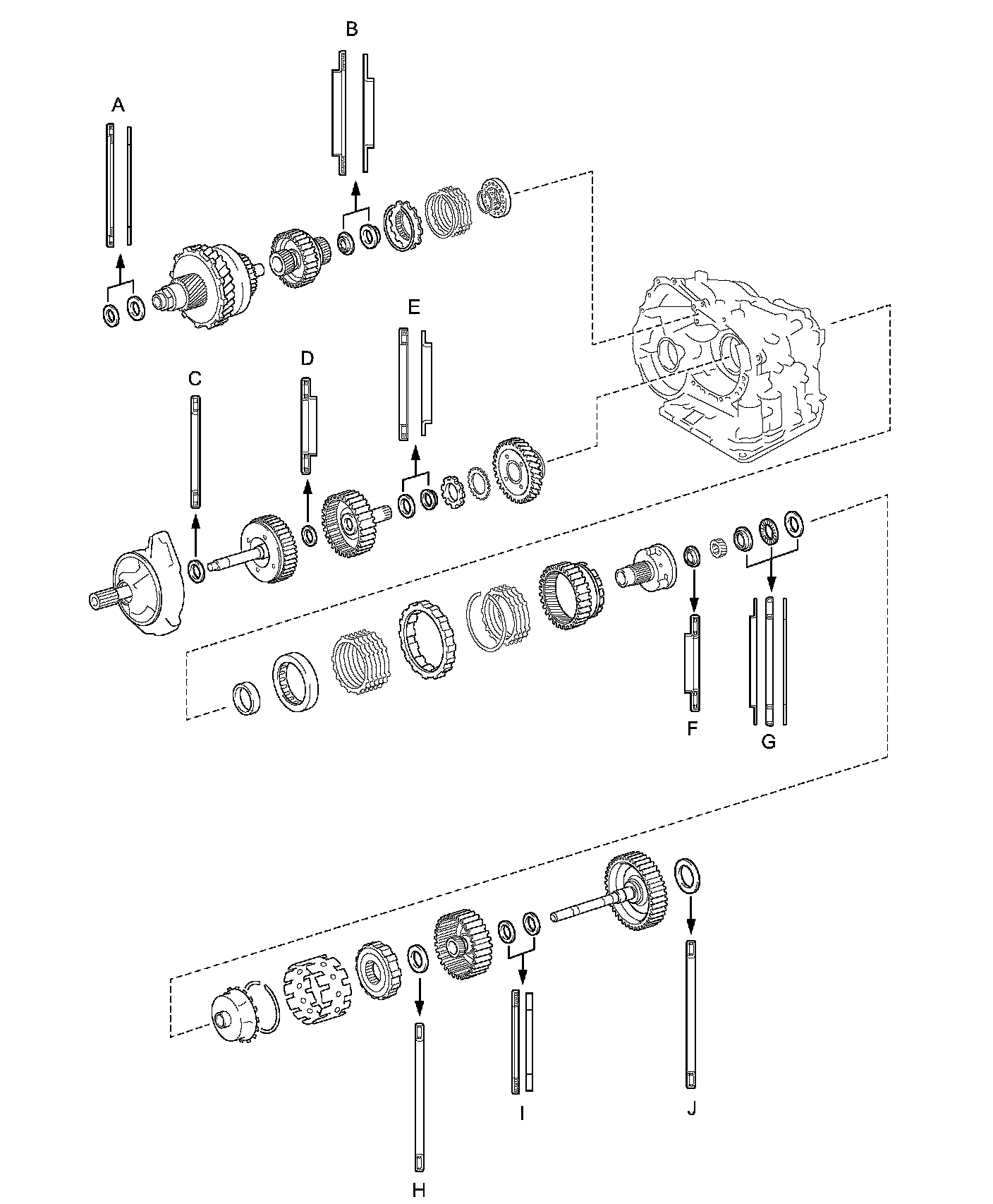
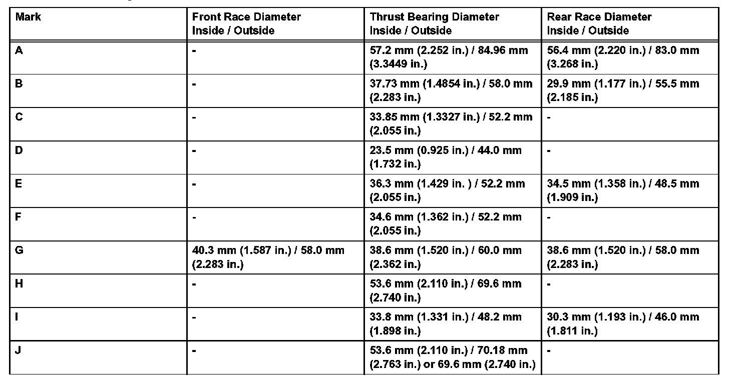
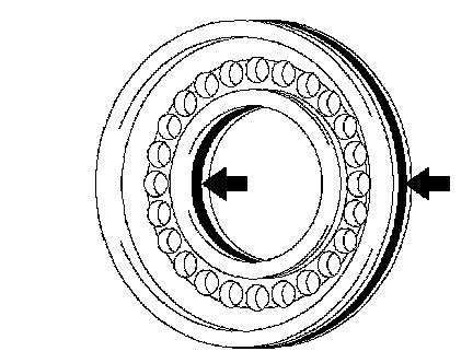
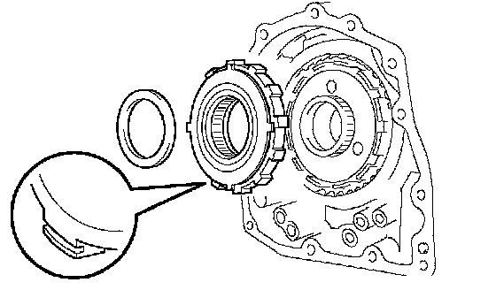
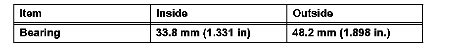
1. BEARING POSITION
Standard Bearing Position:
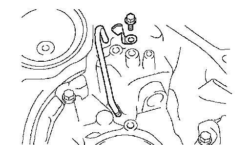
2. INSTALL DIFFERENTIAL GEAR LUBE APPLY TUBE
a. Install the apply tube and clamp to the transaxle housing with the bolt.
Torque: 9.8 Nm (100 kgf-cm, 87 inch lbs.)
NOTICE: Make sure to insert the pipe to the stopper.
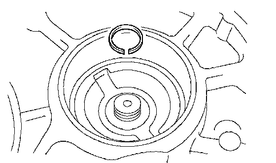
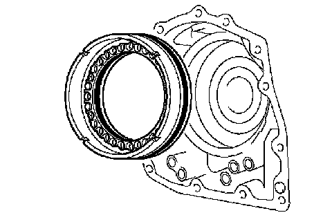
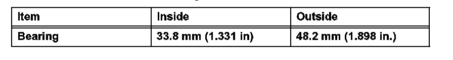
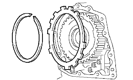
3. INSTALL UNDERDRIVE OUTPUT SHAFT OIL SEAL RING
a. Install a new oil seal ring to the transaxle housing.
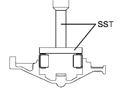
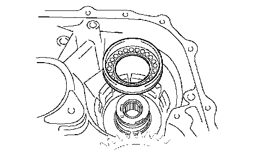
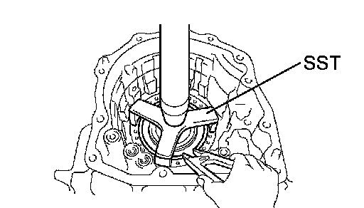
4. INSTALL UNDERDRIVE CYLINDRICAL ROLLER BEARING
a. Using SST and a press, press in the underdrive cylindrical roller bearing.
SST 09950-60020 (09951-00810), 09950-70010 (09951-07100)
NOTICE: Do not apply excessive pressure.
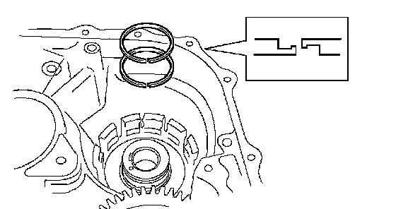
5. INSTALL UNDERDRIVE CLUTCH DRUM OIL SEAL RING
a. Install 2 new oil seal rings to the transaxle.
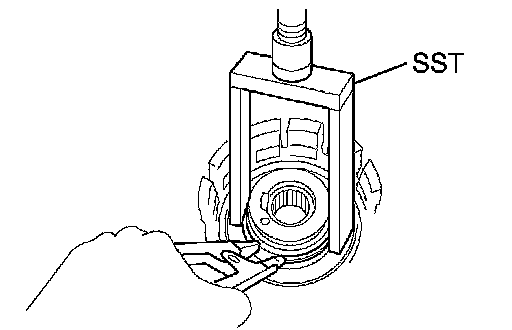
6. INSTALL UNDERDRIVE BRAKE PISTON
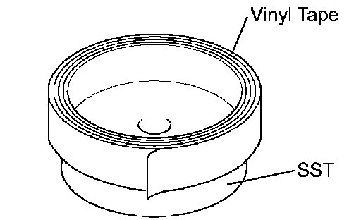
a. Wind a vinyl tape around SST at the place 4.0 mm (0.157 inch) above from the bottom end until the thickness of the wound tape is about 5.0 mm (0.197 inch).
SST 09950-60010 (09951-00320)
NOTICE: Clean SST to remove deposited oil before winding a vinyl tape.
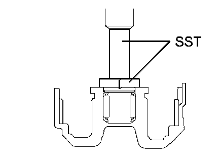
b. Using SST and a press, press in the needle-roller bearing to the transaxle until the wound vinyl tape contacts the transaxle case.
SST 09950-60010 (09951-00320), 09950-70010 (09951-07100)
c. Coat 2 new O-rings with ATF, and install them to the underdrive brake piston.
d. Install the underdrive brake piston to the transaxle.
e. Using SST, a snap ring expander and press, press in the piston return spring and snap ring to the transaxle.
SST 09387-00020
NOTICE: Do not apply excessive pressure.
7. INSTALL NO. 2 BREATHER PLUG
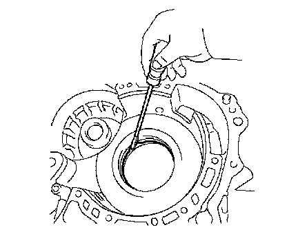
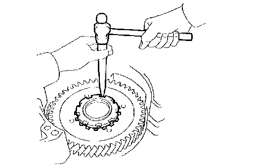
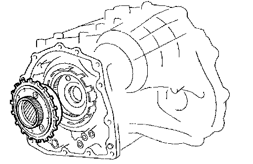
8. INSTALL COUNTER DRIVE GEAR HOLE SNAP RING
a. Using a screwdriver, press in the snap ring to the transaxle.
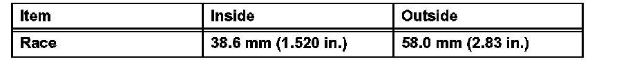
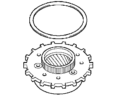
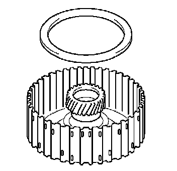
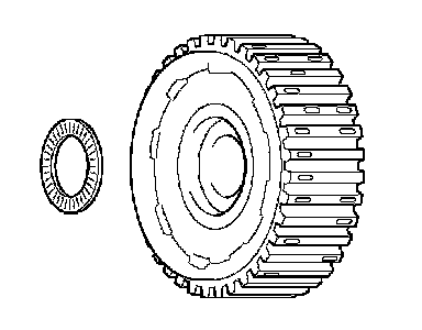
9. INSTALL COUNTER DRIVE GEAR
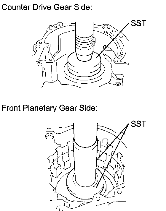
a. Using SST and a press, press in the 2 bearings outer races to the transaxle.
SST 09950-60020 (09951-00890), 09950-70010 (09951-07150)
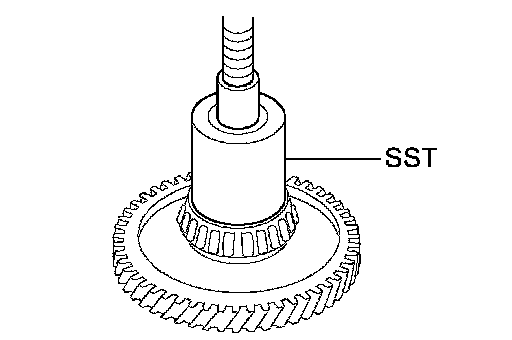
b. Using SST and a press, press in the tapered roller bearing to the counter drive gear until the bearing race contacts with the snap ring.
NOTICE: Do not apply excessive pressure.
SST 09649-17010
c. Using SST and a press, install the counter drive gear and bearing to the transaxle.
SST 09950-70010 (09951-07150), 09950-60020 (09951-00750)
NOTICE: Do not apply excessive pressure.
10. INSTALL 1ST AND REVERSE BRAKE PISTON
a. Coat 2 new O-rings with ATF.
b. Install the 2 O-ring to the 1st and reverse brake piston.
c. Coat the 1st and reverse brake piston with ATF, and install it to the transaxle.
11. INSTALL 1ST AND REVERSE BRAKE RETURN SPRING SUB-ASSEMBLY
a. Using SST, a press and snap ring expander, press the piston return spring and snap ring to the transaxle.
SST 09387-00070
NOTICE:
^ Stop the press when the spring sheet is lowered to the place 1 to 2 mm (0.039 to 0.078 inch) from the snap ring groove, preventing the spring sheet from being deform.
^ Do not expand the snap ring excessively.
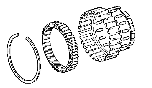
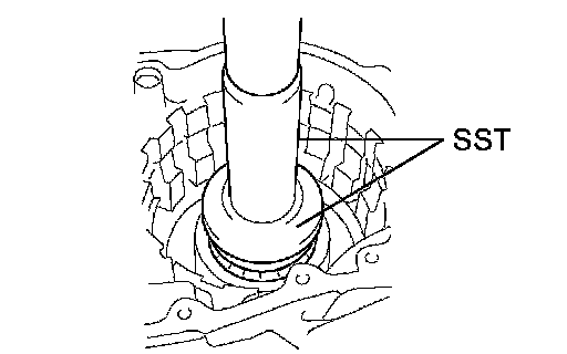
12. INSTALL FRONT PLANETARY RING GEAR
a. Using a screwdriver, install the front planetary ring gear and snap ring to the brake hub.
13. INSTALL FRONT PLANETARY GEAR ASSEMBLY
a. Install the front planetary gear assembly to the brake hub.
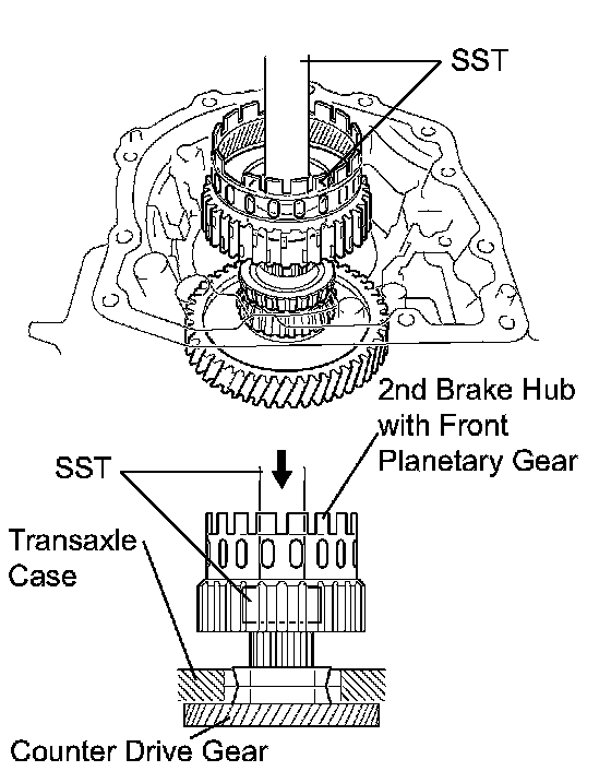
b. Using SST and a press, press-fit the front planetary gear.
SST 09950-60010 (09951-00500), 09950-70010 (09951-07100)
NOTICE: Do not apply excessive pressure.
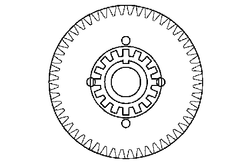
c. Install the washer, as shown in the illustration.
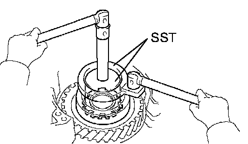
d. Using SST, install the nut.
SST 09387-00030, 09387-00080
Torque: 280 Nm (2,855 kgf-cm, 206 ft. lbs.)
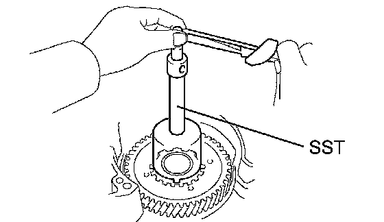
e. Using SST and a torque wrench, measure the turning torque of the bearing while rotating SST at 60 rpm. When the measured value is not within the specified value, gradually tighten the nut until it reaches the specified value.
SST 09387-00080
Torque: Turning torque at 60 rpm
0.51 to 1.02 Nm (5.1 to 10.0 kgf-cm, 4.4 to 8.7 inch lbs.) for new
0.3 to 0.5 Nm (3.1 to 5.1 kgf-cm, 27 to 4.4 inch lbs.) for used
HINT: Use a torque wrench with a fulcrum length of 160 mm (6.3 inch).
f. Using a chisel and hammer, stake the front planetary gear washer.
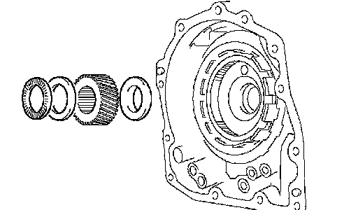
14. INSTALL INPUT SUN GEAR
a. Install the 2 thrust bearings, bearing race and front planetary sun gear to the front planetary gear.
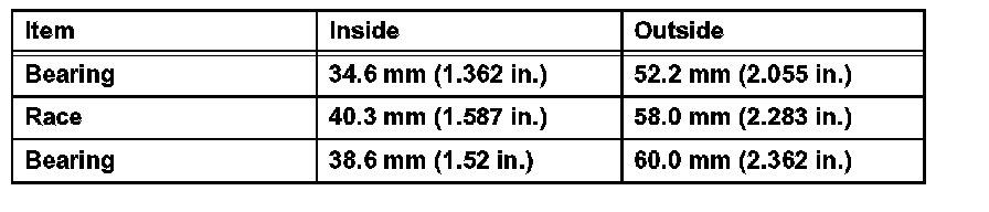
Standard Bearing And Race Diameter:
15. INSTALL REAR PLANETARY GEAR ASSEMBLY
a. Coat the bearing race with ATF, and install it to the rear planetary gear assembly.
Standard Bearing Race Diameter:
b. Install the No. 2 thrust washer.
c. Install the rear planetary gear to the rear planetary ring gear.
d. Using a screwdriver, install the snap ring.
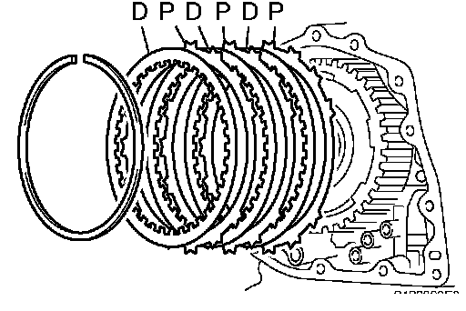
16. INSTALL 1ST AND REVERSE BRAKE CLUTCH DISC
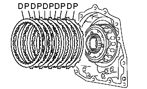
a. Install the 5 plates and 5 discs.
Install in order: P-D-P-D-P-D-P-D-P-D
HINT:
P = Plate
D = Disc
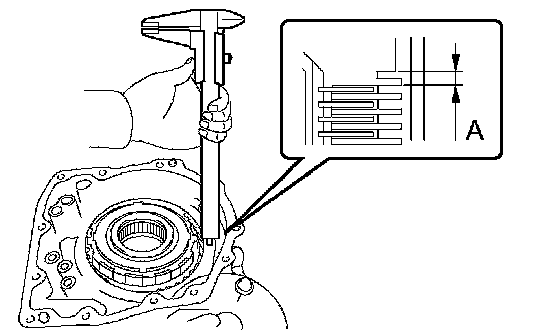
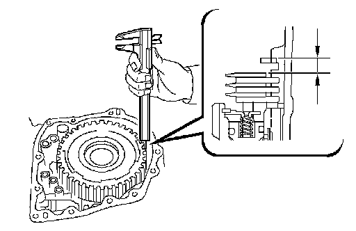
b. Using a vernier caliper, measure the distance between the disc surface and the contact surface of the 2nd brake cylinder and transaxle (Dimension A).
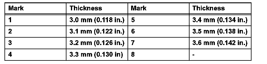
c. Select an appropriate flange so that the pack clearance will meet the specified value. 0.745 to 1.21 mm (0.0293 to 0.0476 inch)
HINT: Piston stroke = Dimension A - Flange thickness
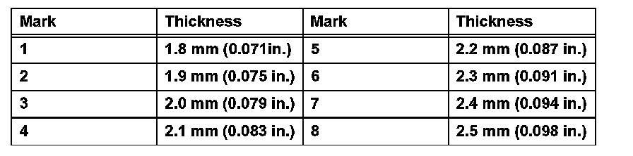
Standard Flange Thickness:
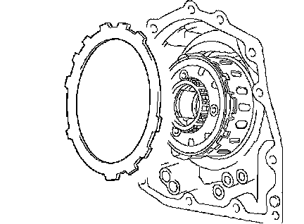
d. Install the flange.
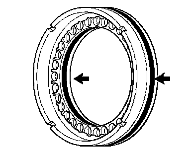
17. INSTALL 2ND BRAKE PISTON ASSEMBLY
a. Install the 2nd brake piston to the transaxle.
b. Install the snap ring and measure the inside diameter.
Standard inside diameter: More than 167 mm (6.57 inch)
NOTICE:
^ Because the taper snap ring has the positioning direction, check it when installing.
^ When the diameter does not satisfy the specified value, replace the snap ring with a new one.
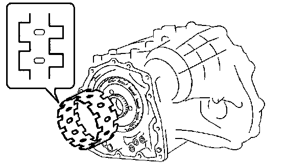
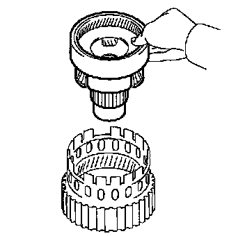
18. INSTALL 1-WAY CLUTCH SLEEVE OUTER
a. Install the 1-way clutch outer sleeve to the 2nd brake cylinder.
NOTICE: Check the positioning direction of the outer sleeve.
19. INSTALL 1-WAY CLUTCH ASSEMBLY
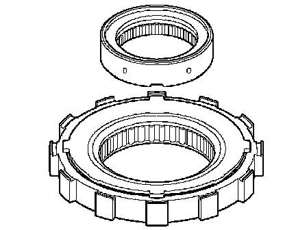
a. Install the inner race to the 1-way clutch.
NOTICE: Check the direction of the inner race.
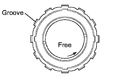
b. Check the rotating direction of the 1-way clutch for the lock or free operation, as shown in illustration.
c. Install the 1-way clutch and bearing to the 1-way clutch sleeve outer.
Standard Bearing Diameter:
NOTICE: Install the thrust bearing properly so that no colored race will be visible.
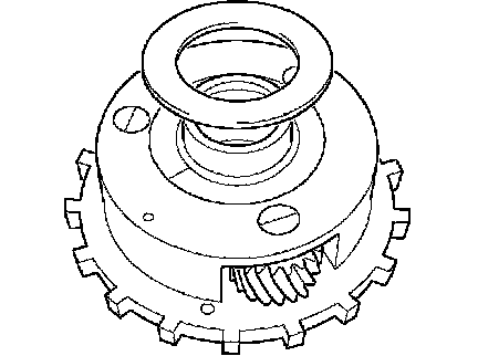
20. INSTALL REAR PLANETARY SUN GEAR ASSEMBLY
a. Coat the No. 1 thrust washer with petroleum jelly, and install it onto the rear planetary sun gear.
b. Coat the bearing with petroleum jelly, and install it onto the rear planetary sun gear.
Standard Bearing Diameter:
c. Install the rear planetary sun gear to the rear planetary gear.
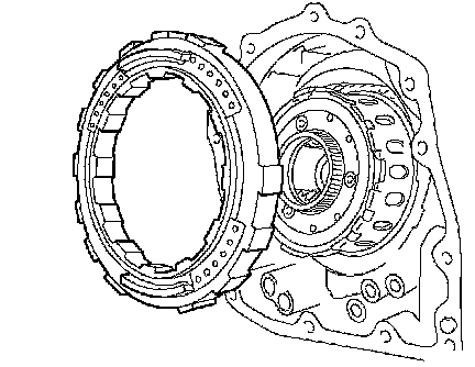
21. INSTALL 2ND BRAKE CLUTCH DISC
a. Install the 3 discs and 3 plates to the transaxle.
Standard install in order: P-D-P-D-P-D
HINT:
P = Plate
D = Disc
b. Temporarily install the snap ring.
c. Using a vernier caliper, measure the distance between the disc surface and snap ring surface.
d. Select an appropriate flange so that the pack clearance will meet the specified value.
Standard pack clearance: 0.50 to 0.91 mm (0.0197 to 0.0358 inch)
HINT: Piston stroke = Clearance - Flange thickness - Snap ring thickness 1.6 mm (0.063 inch)
Standard Flange Thickness:
e. Temporarily remove the snap ring, attach the selected flange and restore the snap ring.
NOTICE: Secure the snap ring so that its gap is visible through the groove of the transaxle case.