Timing Belt: Service and Repair
TIMING BELTComponents:
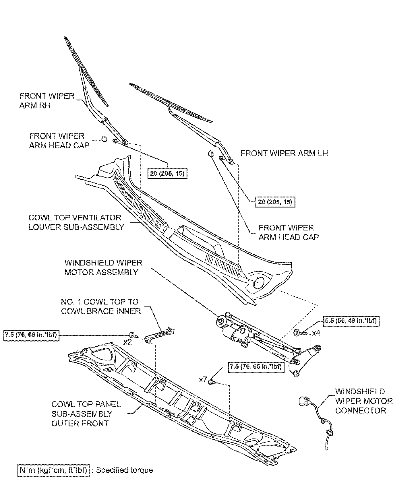
Components:
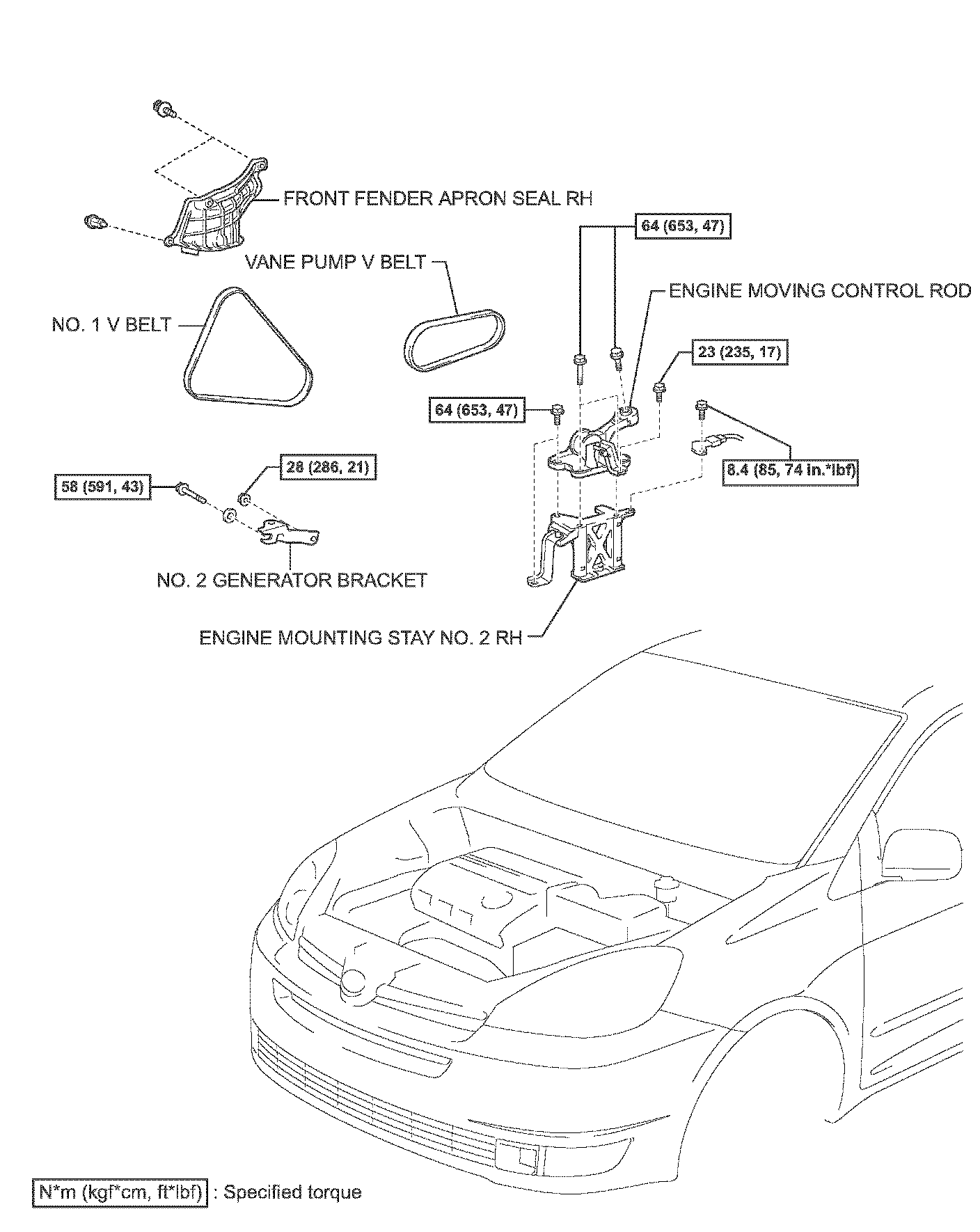
Components:
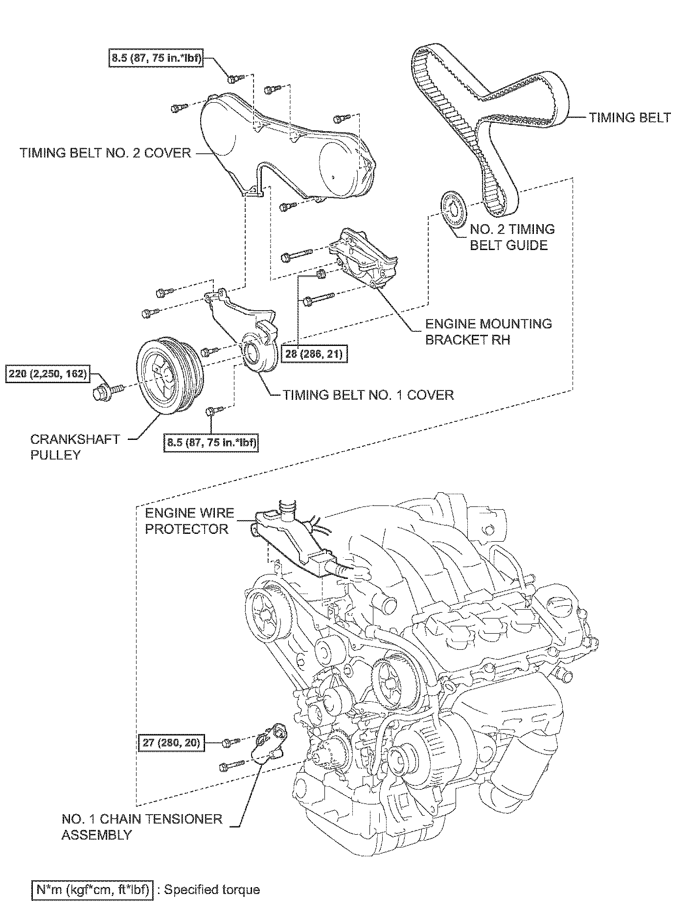
REMOVAL
1. REMOVE FRONT WHEEL RH
2. REMOVE FRONT WIPER ARM HEAD CAP
3. REMOVE FRONT WIPER ARM RH
4. REMOVE FRONT WIPER ARM LH
5. REMOVE COWL TOP VENTILATOR LOUVER SUB-ASSEMBLY
6. REMOVE WIPER LINK ASSEMBLY
7. REMOVE NO. 1 COWL TOP TO COWL BRACE INNER
8. REMOVE COWL TOP PANEL SUB-ASSEMBLY OUTER FRONT
9. REMOVE FRONT FENDER APRON SEAL RH
10. REMOVE NO. 1 V (COOLER COMPRESSOR TO CRANKSHAFT PULLEY) BELT
11. REMOVE VANE PUMP V BELT
12. REMOVE ENGINE MOVING CONTROL ROD
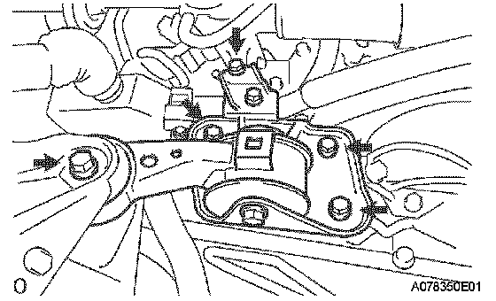
a) Remove the 5 bolts, the engine moving control rod and the engine mounting stay.
13. REMOVE ENGINE MOUNTING STAY NO. 2 RH
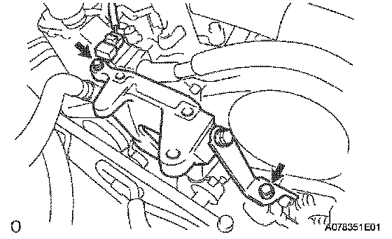
a) Remove the bolt and the wire harness bracket.
b) Remove the bolt, the No. 2 engine mounting stay and the No. 2 engine mounting bracket.
14. REMOVE NO. 2 GENERATOR BRACKET
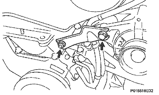
a) Remove the nut and the generator bracket.
15. REMOVE CRANKSHAFT PULLEY
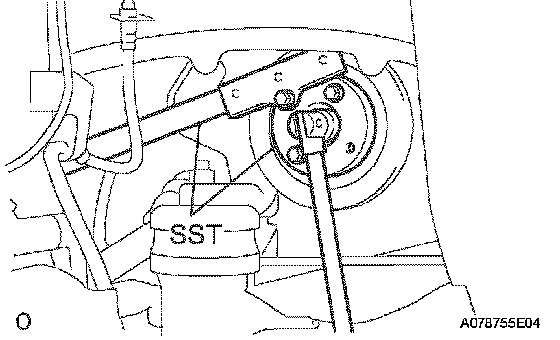
a) Using SST, loosen the pulley bolt.
SST 09213-54015 (91651-60855), 09330-00021
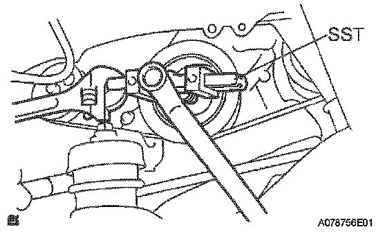
b) Using SST and the pulley bolt, remove the pulley.
SST 09950-50013 (09951-05010, 09952-05010, 09953-05020, 09954-05031)
NOTICE: Before using SST, apply lubricating oil on the threads and tip of the center bolt 150.
16. REMOVE TIMING BELT NO. 1 COVER
17. REMOVE TIMING BELT NO. 2 COVER
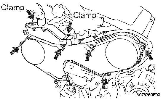
a) Disconnect the engine wire protector clamps from the timing belt No. 3 cover.
b) Remove the 5 bolts and the timing belt cover.
18. REMOVE ENGINE MOUNTING BRACKET RH
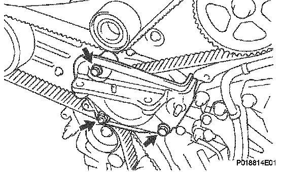
a) Remove the 2 bolts, the nut and the engine mounting bracket RH.
19. REMOVE NO. 2 TIMING BELT GUIDE
20. REMOVE TIMING BELT
a) Set No. 1 cylinder to TDC/compression.
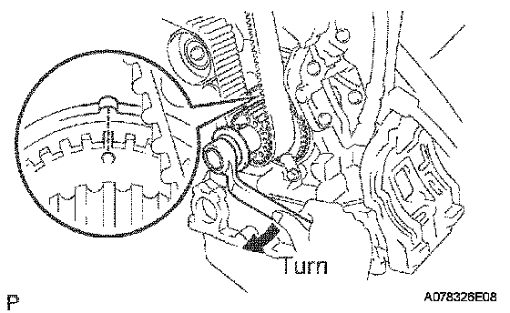
1) Temporarily install the crankshaft pulley bolt and the washer to the crankshaft.
2) Turn the crankshaft clockwise, and align the timing marks of the crankshaft timing pulley and the oil pump body.
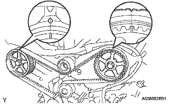
3) Check that timing marks of the camshaft timing pulleys and No. 3 timing belt cover are aligned. If not, turn the crankshaft 1 revolution (360°).
4) Remove the crankshaft pulley bolt.
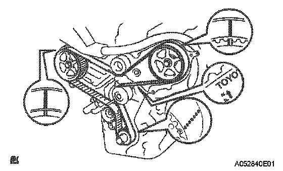
b) If re-using the timing belt, check that there are 3 installation marks on the timing belt as shown in the illustration.
1) If the installation marks have disappeared, put new installation mark on the timing belt before removing.
c) Set No. 1 cylinder to approximately 60° BTDC/ compression.
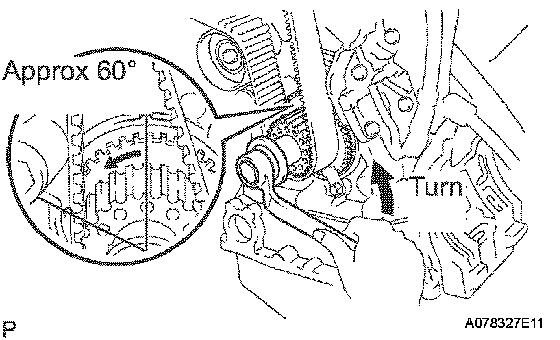
1) Turn the crankshaft counterclockwise by approximately 60°.
NOTICE: If the timing belt is disengaged, having the crankshaft pulley at the wrong angle can cause the piston head and valve head to come into contact with each other when you remove the camshaft timing pulley and camshaft, causing damage. So always set the crankshaft pulley at the correct angle.
d) Remove the timing belt tensioner.
NOTICE: Do not install the tensioner as it removed.
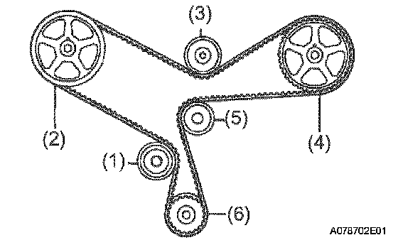
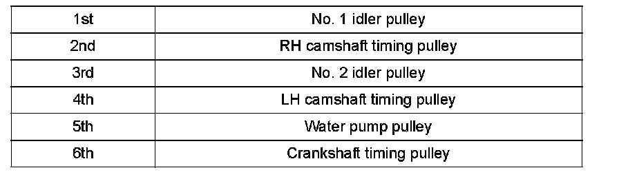
e) Remove the timing belt in this order.
INSTALLATION
1. INSTALL TIMING BELT
a) Remove any oil or water on the pulleys, and keep them clean.
NOTICE:
^ If there is a trace of water and/or oil on the timing belt, repair the leakage and install a new timing belt.
^ Wipe only the pulleys; do not use any cleaning agent.
b) Inspect the idler pulleys.
1) Check that the idler pulley turns smoothly.
2) Visually check the seal portion of the idler pulley for oil leakage.
c) Inspect the water pump.
1) Turn the pulley, and check that water pump bearing moves smoothly and does not make noise.
2) Visually check the drain hole for coolant leakage.
d) Temporarily install the crankshaft pulley bolt and the washer to the crankshaft.
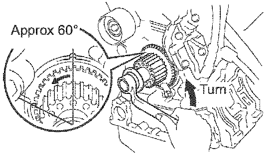
e) Turn the crankshaft counterclockwise by approximately 60°.
NOTICE: To prevent contacting the piston head and the valve head, set the crankshaft pulley at 60° BTDC/compression position.
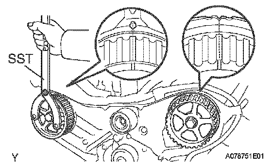
f) Using SST turn the camshaft pulley, and align the timing marks of the timing pulley and the No. 3 timing belt cover.
SST 09960-10010 (09962-01000, 09963-01000)
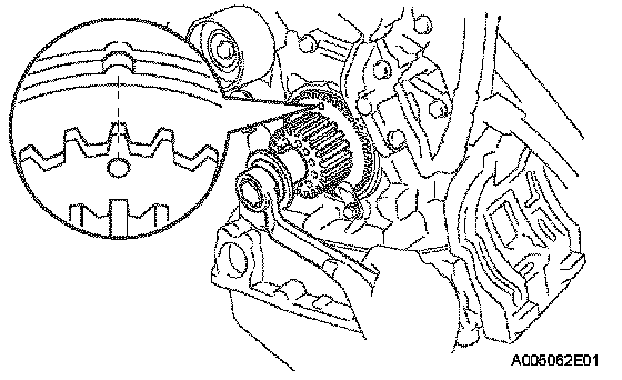
g) Turn the crankshaft, and align the timing marks of the crankshaft timing pulley and the oil pump body.
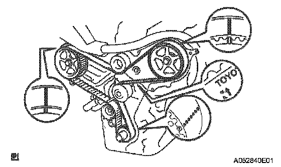
h) Face the front mark on the timing belt forward.
i) Align the installation mark on the timing belt with the timing mark of the crankshaft timing pulley.
j) Align the installation marks on the timing belt with the timing marks of the camshaft timing pulleys.


k) Install the timing belt in this order.
2. INSTALL NO. 1 CHAIN TENSIONER ASSEMBLY
a) Set the timing belt tensioner upright on the press.

b) Slowly press in the push rod.
NOTICE: Do not apply pressure more than 9.8 kN (1,000 kgf, 2,205 ft. lbs.) to the rod.
c) Align the holes of the push rod and housing, pass a 1.5 mm hexagon wrench through the holes to keep the setting position of the push rod.
d) Release the press.
e) Temporarily install the tensioner with the 2 bolts. Alternately tighten the 2 bolts.
Torque: 27 Nm (280 kgf-cm, 20 ft. lbs.)
NOTICE: Be sure to tighten the bolts equally. Installing the tensioner at an angle may cause failure of its proper operation.
f) Remove the 1.5 mm hexagon wrench from the tensioner.
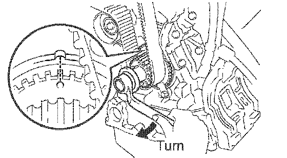
g) Turn the crankshaft 2 revolutions slowly and align the timing marks of the crankshaft timing pulley and the oil pump body.
NOTICE: Always turn the crankshaft clockwise.
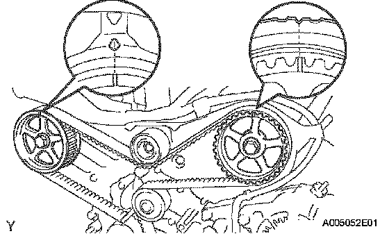
h) Check the timing marks of the RH and LH timing pulleys are aligned with the timing marks of the No. 3 timing belt cover as shown in the illustration. If the marks do not align, remove the timing belt and reinstall it.
i) Remove the crankshaft pulley bolt.
3. INSTALL NO. 2 TIMING BELT GUIDE
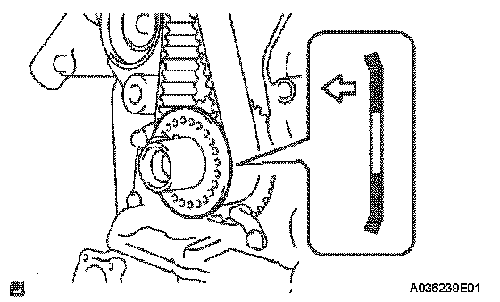
a) Install the timing belt guide, facing the cup side toward the engine front.
4. INSTALL ENGINE MOUNTING BRACKET RH
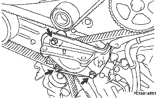
a) Install the engine mounting bracket RH with the 2 bolts and the nut.
Torque: 28 Nm (286 kgf-cm, 21 ft. lbs.)
5. INSTALL TIMING BELT NO. 2 COVER
a) Visually check for cracks and breaks in the gasket of the timing belt cover.
If there is a trace that water is entering at the visual check, replace the timing belt cover.
b) Install the timing belt cover.
Torque: 8.5 Nm (87 kgf-cm, 75 inch lbs.)
6. INSTALL TIMING BELT NO. 1 COVER
a) Visually check for cracks and breaks in the gasket of the timing belt cover.
If there is a trace that water is entering at the visual check, replace the timing belt cover.
b) Install the timing belt cover.
Torque: 8.5 Nm (87 kgf-cm, 75 inch lbs.)
c) Install the engine wire protector cover to the timing belt No. 3 cover.
7. INSTALL CRANKSHAFT PULLEY

a) Align the keyway of the pulley with the key located on the crankshaft and slide the pulley into place.
b) Using SST, install the pulley bolt.
SST 09213-54015 (91651-60855), 09330-00021
Torque: 220 Nm (2250 kgf-cm, 162 ft. lbs.)
8. INSTALL NO. 2 GENERATOR BRACKET
Torque: 28 Nm (286 kgf-cm, 21 ft. lbs.)
9. INSTALL ENGINE MOUNTING STAY NO. 2 RH
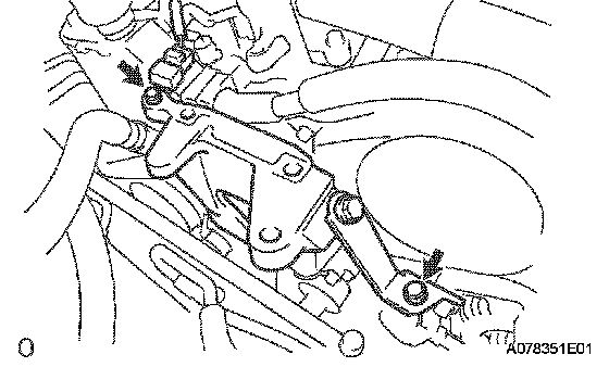
a) Install the No. 2 engine mounting stay and the No. 2 engine mounting bracket with the bolt.
Torque: 64 Nm (653 kgf-cm, 47 ft. lbs.)
b) Install the wire harness bracket with the bolt.
Torque: 8.4 Nm (85 kgf-cm, 74 inch lbs.)
10. INSTALL ENGINE MOVING CONTROL ROD
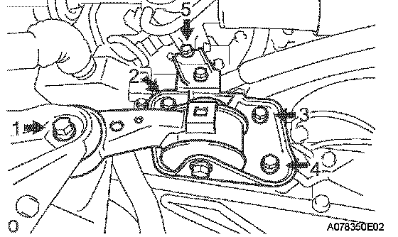
a) Install the engine mounting control rod and the engine mounting stay with the 5 bolts. Using several steps, tighten the bolts in the sequence shown in the illustration.
Torque:
12 mm head 23 Nm (235 kgf-cm, 17 ft. lbs.)
14 mm head 64 Nm (653 kgf-cm, 47 ft. lbs.)
11. INSTALL VANE PUMP V BELT
12. INSTALL NO. 1 V (COOLER COMPRESSOR TO CRANKSHAFT PULLEY) BELT
13. INSPECT DRIVE BELT DEFLECTION AND TENSION
14. INSTALL COWL TOP PANEL SUB-ASSEMBLY OUTER FRONT
15. INSTALL NO. 1 COWL TOP TO COWL BRACE INNER
16. INSTALL WIPER LINK ASSEMBLY
17. INSTALL FRONT WIPER ARM LH
18. INSTALL FRONT WIPER ARM RH
19. INSTALL FRONT WHEEL RH