Part 2
ENGINE UNITCOMPONENTS:

COMPONENTS:

COMPONENTS:

COMPONENTS:

COMPONENTS:

COMPONENTS:

COMPONENTS:

INSPECTION (STEPS 14-26)
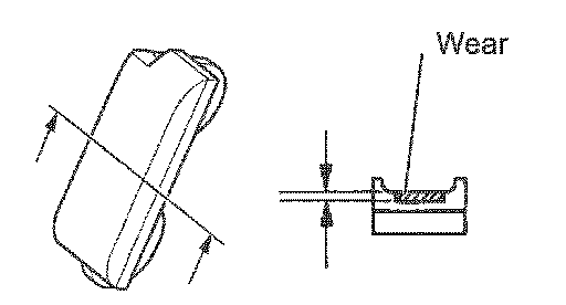
14. INSPECT NO. 3 CHAIN VIBRATION DAMPER
a. Using vernier calipers, measure the vibration damper No. 3 wear.
Maximum wear: 1.0 mm (0.039 inch)
If the wear is greater than the maximum, replace the vibration damper.
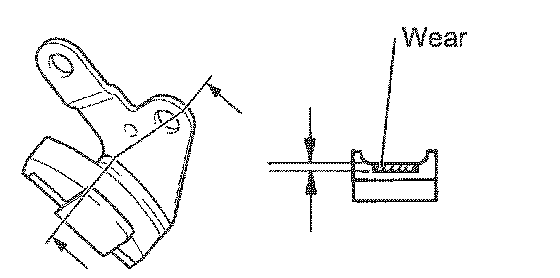
15. INSPECT NO. 4 CHAIN VIBRATION DAMPER
a. Using vernier calipers, measure the vibration damper No. 4 wear.
Maximum wear: 1.0 mm (0.039 inch)
If the wear is greater than the maximum, replace the vibration damper.
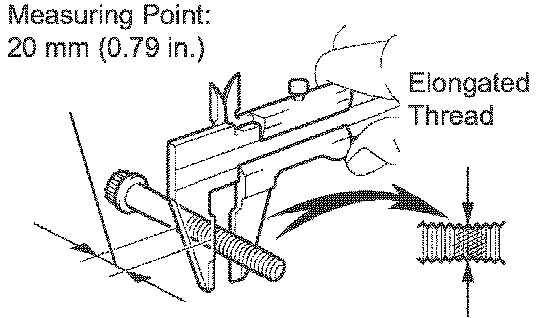
16. INSPECT CYLINDER HEAD SET BOLT
a. Using vernier calipers, measure the minimum diameter of the elongated thread at the measuring point.
Standard outside diameter: 10.76 to 10.97 mm (0.4236 to 0.4319 inch)
Minimum outside diameter: 10.40 mm (0.4094 inch)
HINT:
^ If a visual check reveals no excessively thin areas, check the center of the bolt (see illustration) and find the area that has the lowest diameter.
^ If the diameter is less than the minimum, replace the cylinder head bolt.
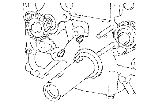
17. INSTALL CRANKSHAFT PULLEY SET CRANKSHAFT KEY
a. Install the 2 pulley keys to the crankshaft.
18. INSTALL NO. 4 CHAIN VIBRATION DAMPER
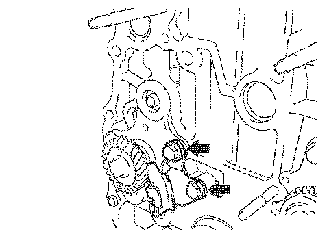
a. Install the vibration damper No. 4 with the 2 bolts.
Torque: 18 Nm (185 kgf-cm, 13 ft. lbs.)
19. INSPECT VALVE LASH ADJUSTER ASSEMBLY
NOTICE:
^ Keep the lash adjuster free from dirt and foreign objects.
^ Only use clean engine oil.
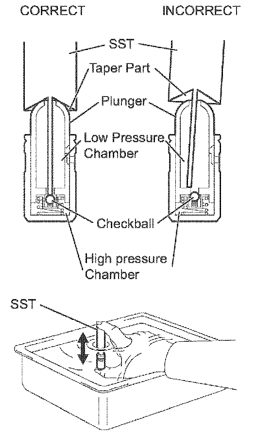
a. Place the lash adjuster into a container full of engine oil.
b. Insert SST's tip into the lash adjuster's plunger and use the tip to press down on the checkball inside the plunger.
SST 09276-75010
c. Squeeze the SST and lash adjuster together to move the plunger up and down 5 to 6 times.
d. Check the movement of the plunger and bleed the air.
OK: Plunger moves up and down.
NOTICE: When bleeding high-pressure air from the compression chamber, make sure that the tip of the SST is actually pressing the checkball as shown in the illustration. If the checkball is not pressed, air will not bleed.
e. After bleeding the air, remove the SST, then quickly and firmly press the plunger with a finger.
OK: Plunger is very difficult to move. If the result is not as specified, replace the lash adjuster.
20. INSPECT CYLINDER HEAD FOR FLATNESS
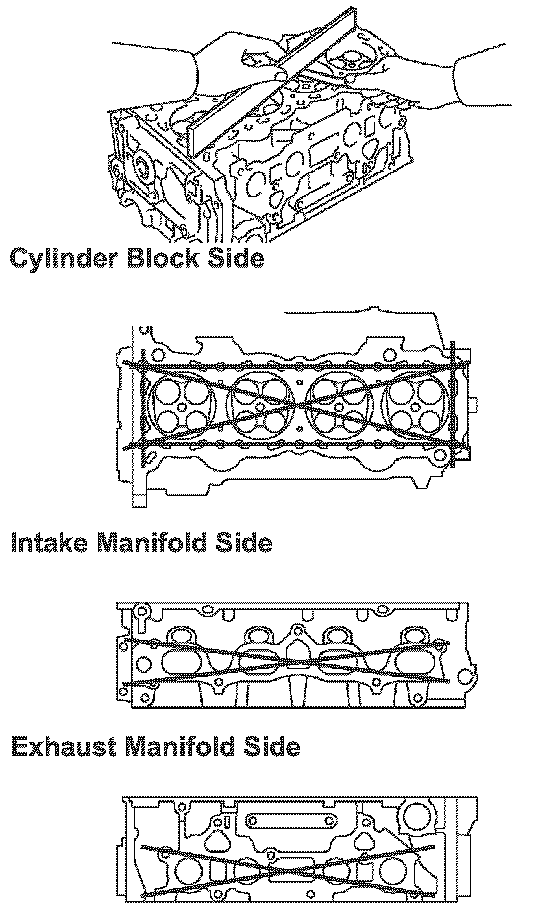
a. Using a precision straight edge and feeler gauge, measure the warpage of the contact surface of contacting the cylinder block and manifolds.
Maximum warpage: 0.05 mm (0.0020 inch)
If the warpage is greater than the maximum, replace the cylinder head.
21. INSPECT CYLINDER HEAD FOR CRACKS
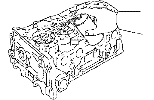
a. Using a dye penetrate, check the intake ports, exhaust ports and cylinder surface for cracks. If cracked, replace the cylinder head.
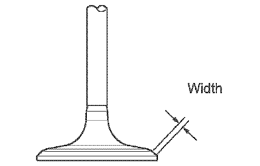
22. INSPECT INTAKE VALVE SEAT
a. Apply a light coat of Prussian blue (or equivalent) to the valve face.
b. Lightly press the valve face against the valve seat.
c. Check the valve face and valve seat by using this procedure.
(1) If Prussian blue appears around the entire valve face, the valve face is concentric. If not, replace the valve.
(2) If Prussian blue appears around the entire valve seat, the guide and valve face are concentric. If not, resurface the valve seat.
(3) Check that the valve seat contacts in the middle of the valve face with the width between 1.0 and 1.4 mm (0.039 and 0.055 inch).
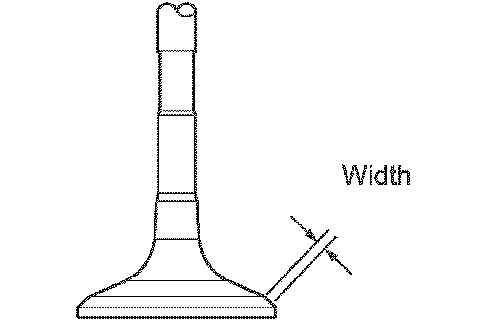
23. INSPECT EXHAUST VALVE SEAT
a. Apply a light coat of Prussian blue (or equivalent) to the valve face.
b. Lightly press the valve face against the valve seat.
c. Check the valve face and valve seat by using to this procedure.
(1) If Prussian blue appears around the entire valve face, the valve face is concentric. If not, replace the valve.
(2) If Prussian blue appears around the entire valve seat, the guide and valve face are concentric. If not, resurface the valve seat.
(3) Check that the valve seat contacts in the middle of the valve face with the width between 1.0 and 1.4 mm (0.039 and 0.055 inch).
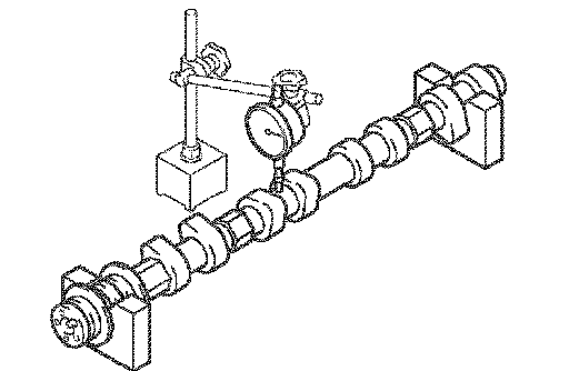
24. INSPECT CAMSHAFT
a. Check the camshaft for runout.
(1) Place the camshaft on V-blocks.
(2) Using a dial indicator, measure the circle runout at the center journal.
Maximum circle runout: 0.03 mm (0.0012 inch)
If the circle runout is greater than the maximum, replace the camshaft.
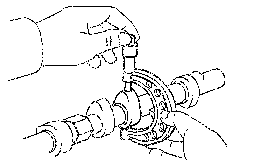
b. Using a micrometer, measure the cam lobe height.
Standard cam lobe height: 42.855 to 42.955 mm (1.6872 to 1.6911 inch)
Minimum cam lobe height: 42.855 mm (1.6872 inch)
If the cam lobe height is less than the minimum, replace the camshaft.
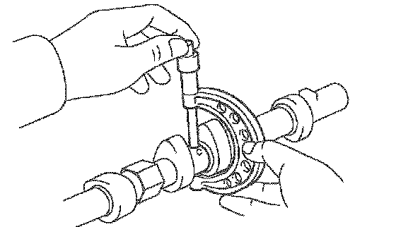
c. Using a micrometer, measure the journal diameter.
Standard Journal Diameter:

If the journal diameter is not as specified, check the oil clearance.
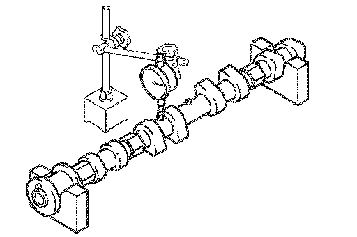
25. INSPECT NO. 2 CAMSHAFT
a. Check the camshaft for runout.
(1) Place the camshaft on V-blocks.
(2) Using a dial indicator, measure the circle runout at the center journal.
Maximum circle runout: 0.03 mm (0.0012 inch)
If the circle runout is greater than the maximum, replace the camshaft.
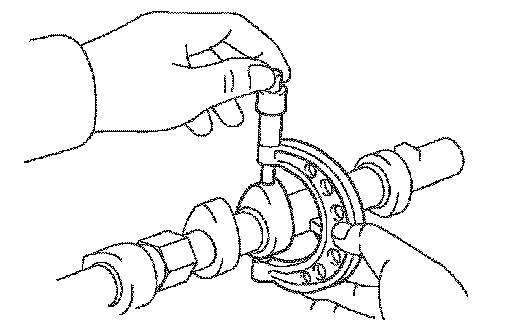
b. Using a micrometer, measure the cam lobe height.
Standard cam lobe height: 42.854 to 42.954 mm (1.687 to 1.6911 inch)
Minimum cam lobe height: 42.854 mm (1.6872 inch)
If the cam lobe height is less than the minimum, replace the camshaft.
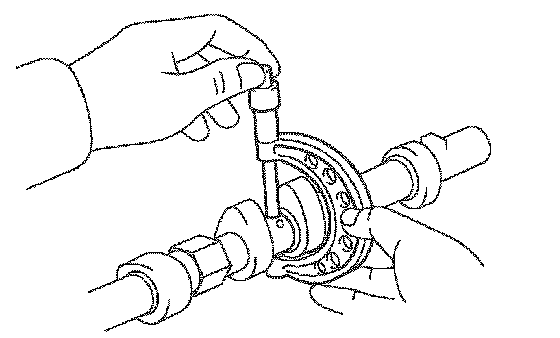
c. Using a micrometer, measure the journal diameter.
Standard Journal Diameter:

If the journal diameter is not as specified, check the oil clearance.
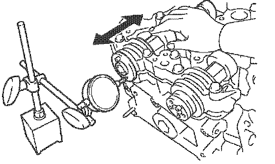
26. INSPECT CAMSHAFT THRUST CLEARANCE
a. Install the camshafts.
b. Using a dial indicator, measure the thrust clearance while moving the camshaft back and forth.
Standard thrust clearance: 0.10 to 0.24 mm (0.004 to 0.009 inch)
Maximum thrust clearance: 0.26 mm (0.010 inch)
If the thrust clearance is greater than the maximum, replace the cylinder head. If the thrust surface is damaged, replace the camshaft.