Cylinder Head Assembly
CYLINDER HEAD SUB-ASSEMBLYThe cylinder head bolts are tightened in 2 successive steps.
Apply a light coat of engine oil to the threads of the cylinder head bolts.
Install and tighten the 10 cylinder head bolts and plate washers uniformly with an 8 mm bi-hexagon wrench, in the sequence shown in the illustration.
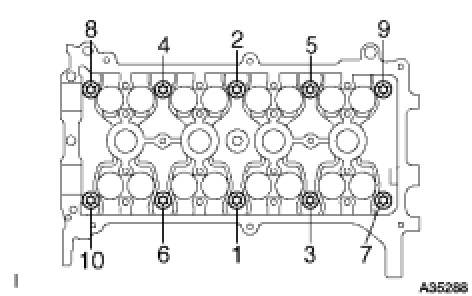
Torque 29 Nm (300 kgf-cm, 22 ft-lbf)
Mark the front of the cylinder head bolt with paint.
Retighten the cylinder head bolts 90° and then an additional 90° as shown in the illustration.
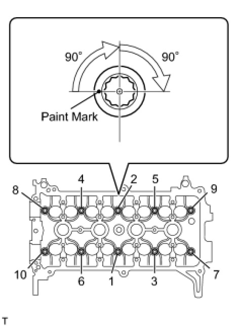
Check that the paint mark is now at a 180° angle from the front.
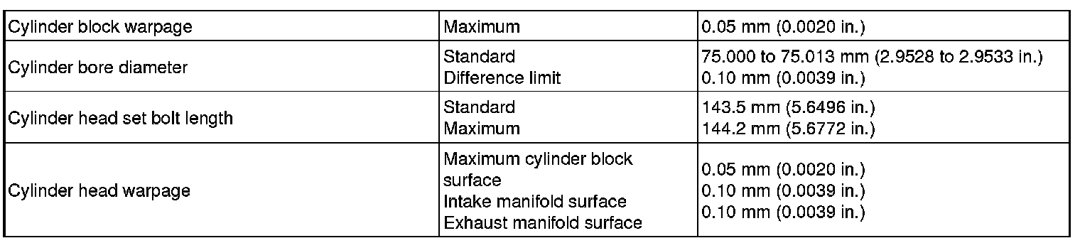
SURFACE VARIATION
Camshaft Bearing Caps
NO. 1 CAMSHAFT
Examine the front marks and numbers and tighten the bolts in the sequence shown in the illustration.
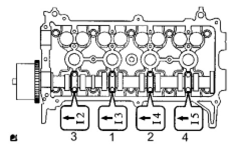
Torque 13 Nm (129 kgf-cm, 9.4 ft-lbf)
NOTICE: Tighten each bolt uniformly while keeping the camshaft level.
NO. 2 CAMSHAFT
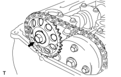
Examine the front marks and numbers on camshaft bearing cap No. 1 and No. 2 and check that the sequence is as shown in the illustration. Then uniformly tighten the bolts, in several steps, in the sequence shown in the illustration.
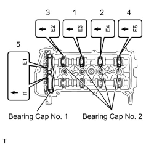
For bearing cap No. 2 - Torque 13 Nm (129 kgf-cm, 9.4 ft-lbf)
For bearing cap No. 1 - Torque 23 Nm (235 kgf-cm, 17 ft-lbf)
NOTICE: Tighten each bolt uniformly while keeping the camshaft level.
Using a wrench, hold the hexagonal lobe of camshaft No. 2 and install the fringe bolt.
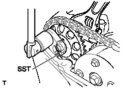
Torque 64 Nm (653 kgf-cm, 47 ft-lbf)
INTAKE MANIFOLD TORQUE & SEQUENCE Specifications
EXHAUST MANIFOLD TORQUE & SEQUENCE Specifications
CAMSHAFT GEAR/SPROCKET TORQUE Specifications