Overhaul
DISASSEMBLY1. REMOVE GENERATOR PULLEY

SST 09820-63010 (09820-06010, 09820-06020)
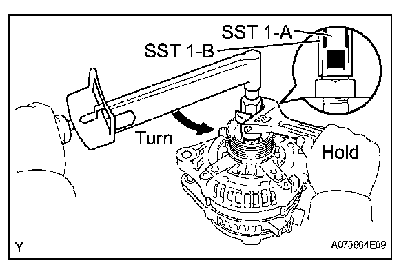
a. Hold SST 1-A with a torque wrench, and tighten SST 1-B clockwise with the specified torque.
Torque: 39 N.m (400 kgf.cm, 29 ft.lbf)
NOTE: Check that SST is secured to the rotor shaft.
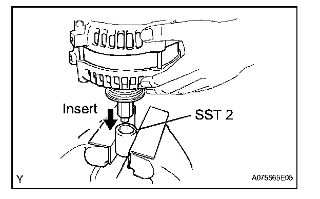
b. Mount SST 2 in a vise.
c. Insert SST 1-A and B into SST 2, and attach the pulley nut to SST 2.
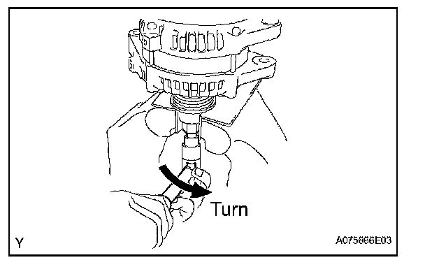
d. To loosen the pulley nut, turn SST 1-A in the direction shown in the illustration.
NOTE: To prevent damage to the rotor shaft, do not loosen the pulley nut more than one-half turn.
e. Remove the generator from SST 2.
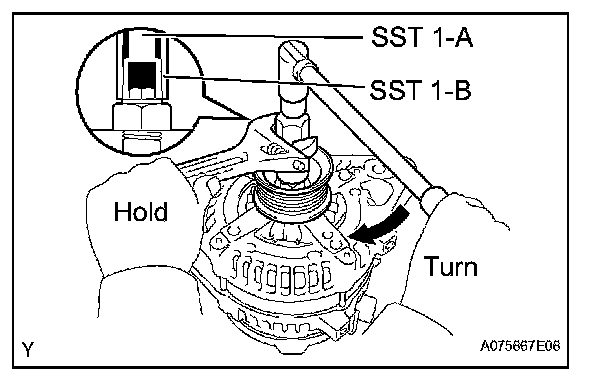
f. Turn SST 1-B, and remove SST 1-A and B.
g. Remove the pulley nut and pulley.
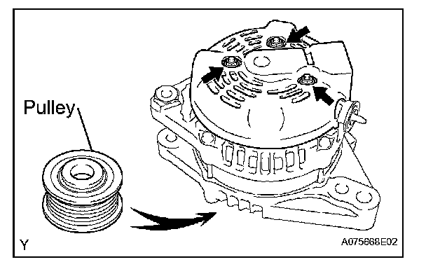
2. REMOVE GENERATOR REAR END COVER
a. Place the generator on the pulley.
b. Remove the 3 nuts and rear end cover.
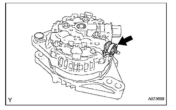
3. REMOVE TERMINAL INSULATOR
a. Remove the terminal insulator.
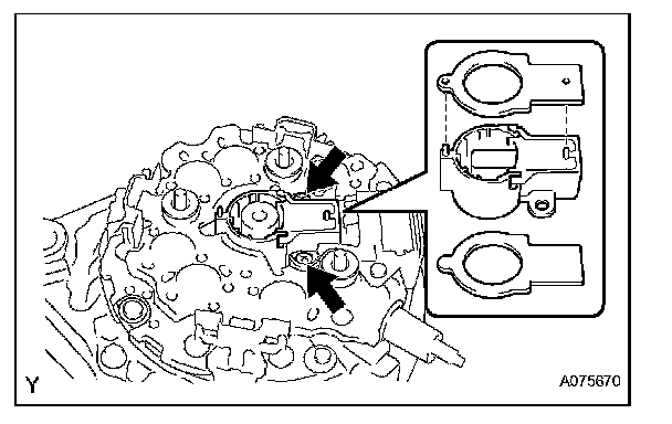
4. REMOVE GENERATOR BRUSH HOLDER ASSEMBLY
a. Remove the plate seal.
b. Remove the 2 nuts and brush holder.
c. Remove the plate seal.
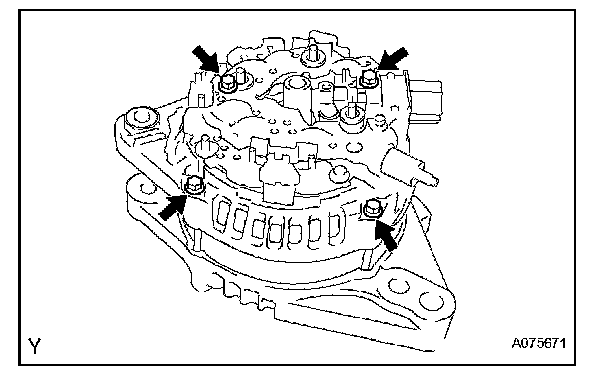
5. REMOVE GENERATOR COIL ASSEMBLY
a. Remove the 4 bolts.
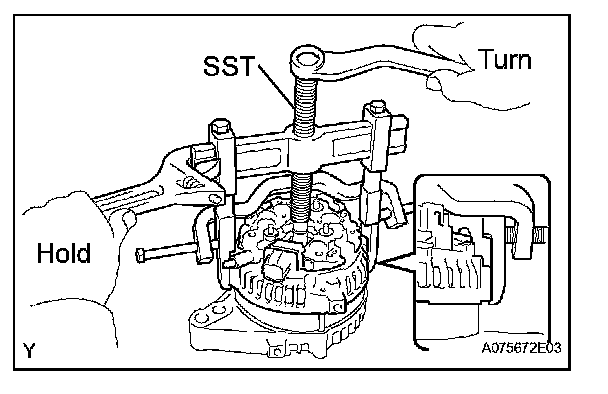
b. Using SST, remove the coil.
SST 09950-40011 (09951-04020, 09952-04010, 09953-04020, 09954-04010, 09955-04071, 09957-04010, 09958-04011)
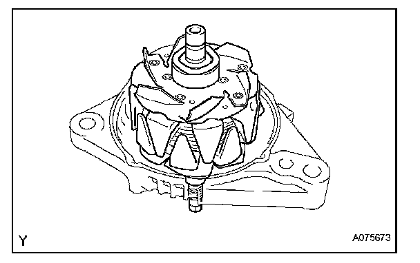
6. REMOVE GENERATOR ROTOR ASSEMBLY
a. Remove the washer and rotor.
REASSEMBLY
1. INSTALL GENERATOR ROTOR ASSEMBLY
a. Place the drive end frame on the rotor.
b. Install the rotor and washer.
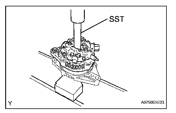
2. INSTALL GENERATOR COIL ASSEMBLY
a. Using SST and a press, press in the coil carefully.
SST 09285-76010
b. Install the 4 bolts.
Torque: 5.8 N.m (59 kgf.cm, 51 in.lbf)
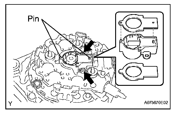
3. INSTALL GENERATOR BRUSH HOLDER ASSEMBLY
a. Install the plate seal (Inside).
b. Place the brush holder with the pin facing upward.
NOTE: Be careful of the brush holder installing direction.
c. Install the 2 screws.
Torque: 1.8 N.m (18 kgf.cm, 16 in.lbf)
d. Align the pins of the brush holder with the holes of the plate seal (outside), and install the plate seal (outside).
4. INSTALL TERMINAL INSULATOR
5. INSTALL GENERATOR REAR END COVER
a. Install the rear end cover with the 3 nuts.
Torque: 4.6 N.m (47 kgf.cm, 41 in.lbf)
6. INSTALL GENERATOR PULLEY

SST 09820-63010 (09820-06010, 09820-06020)
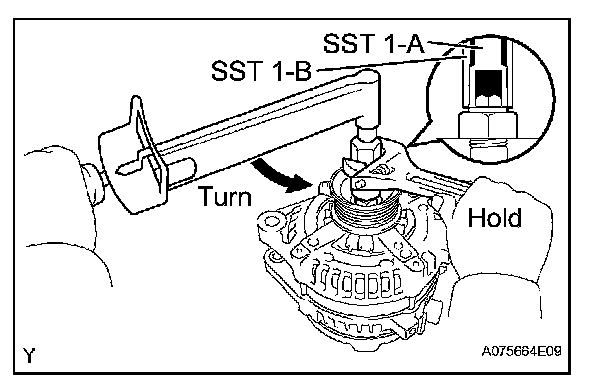
a. Install the pulley to the rotor shaft by tightening the pulley nut by hand.
b. Hold SST 1-A with a torque wrench, and tighten SST 1-B clockwise with the specified torque.
Torque: 39 N.m (400 kgf.cm, 29 ft.lbf)
NOTE: Check that SST is secured to the rotor shaft.
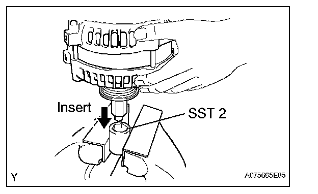
c. Mount SST 2 in a vise.
d. Insert SST 1-A and B into SST 2, and attach the pulley nut to SST 2
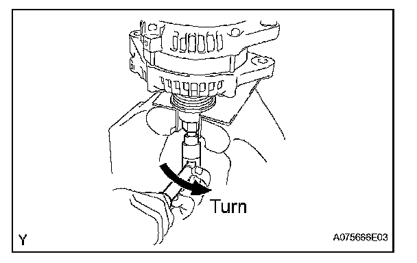
e. Tighten the pulley nut by turning SST 1-A in the direction shown in the illustration.
Torque: 111 N.m (1,125 kgf.cm, 81 ft.lbf)
f. Remove the generator from SST 2.
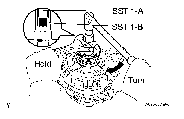
g. Turn SST 1-B, and remove SST 1-A, B.
h. Turn the pulley, and check that the pulley moves smoothly.