Timing Chain: Service and Repair
TIMING CHAINCOMPONENTS (Part 1):
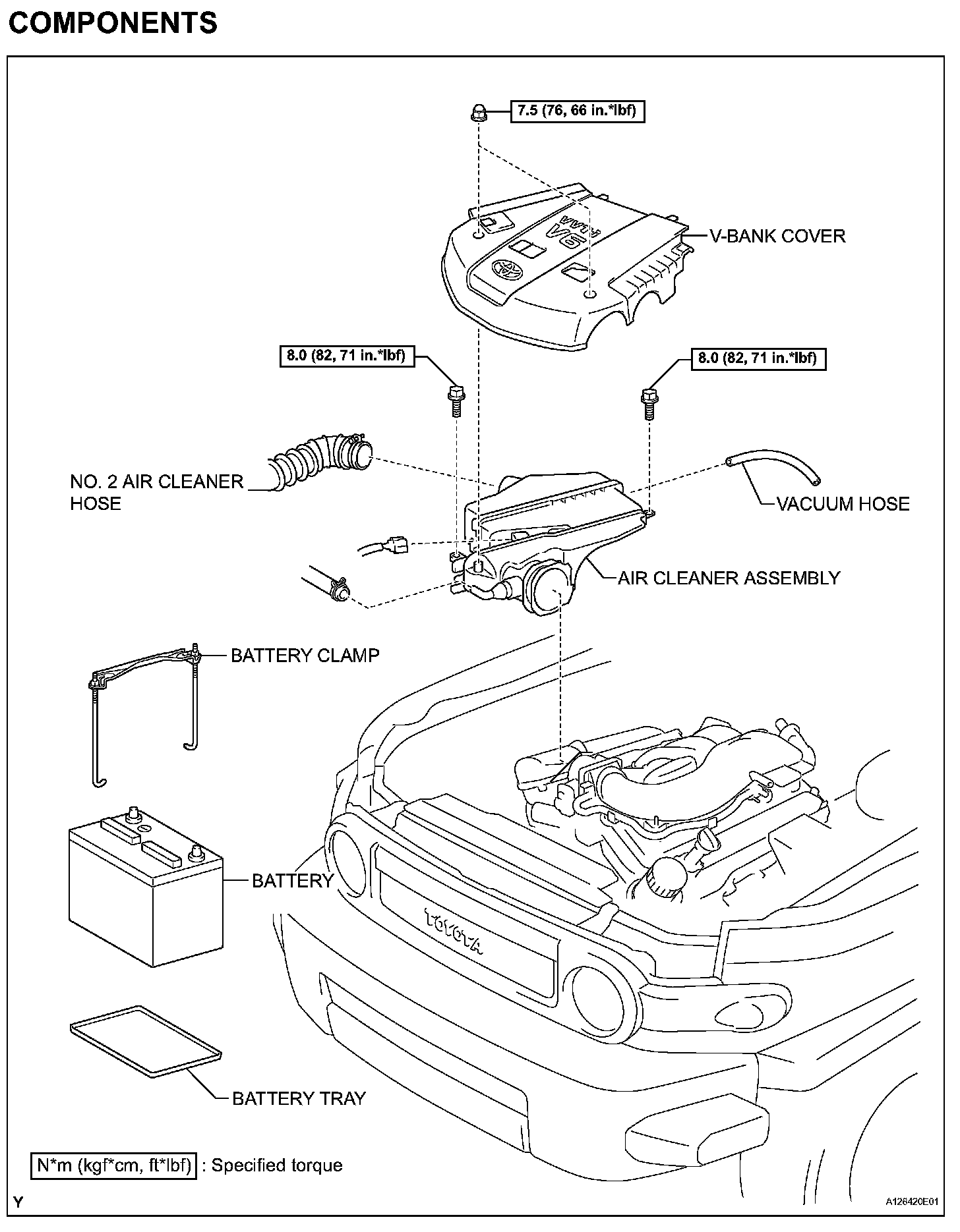
COMPONENTS (Part 2):
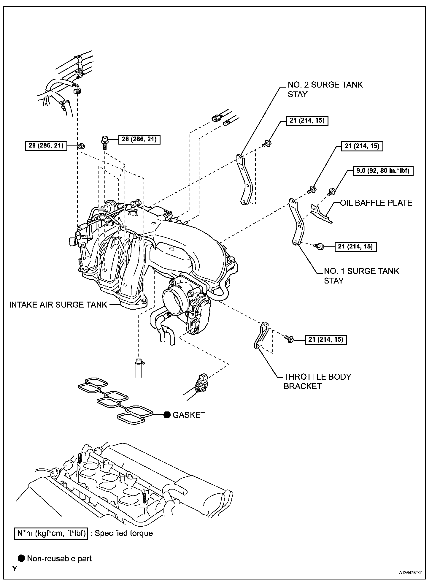
COMPONENTS (Part 3):
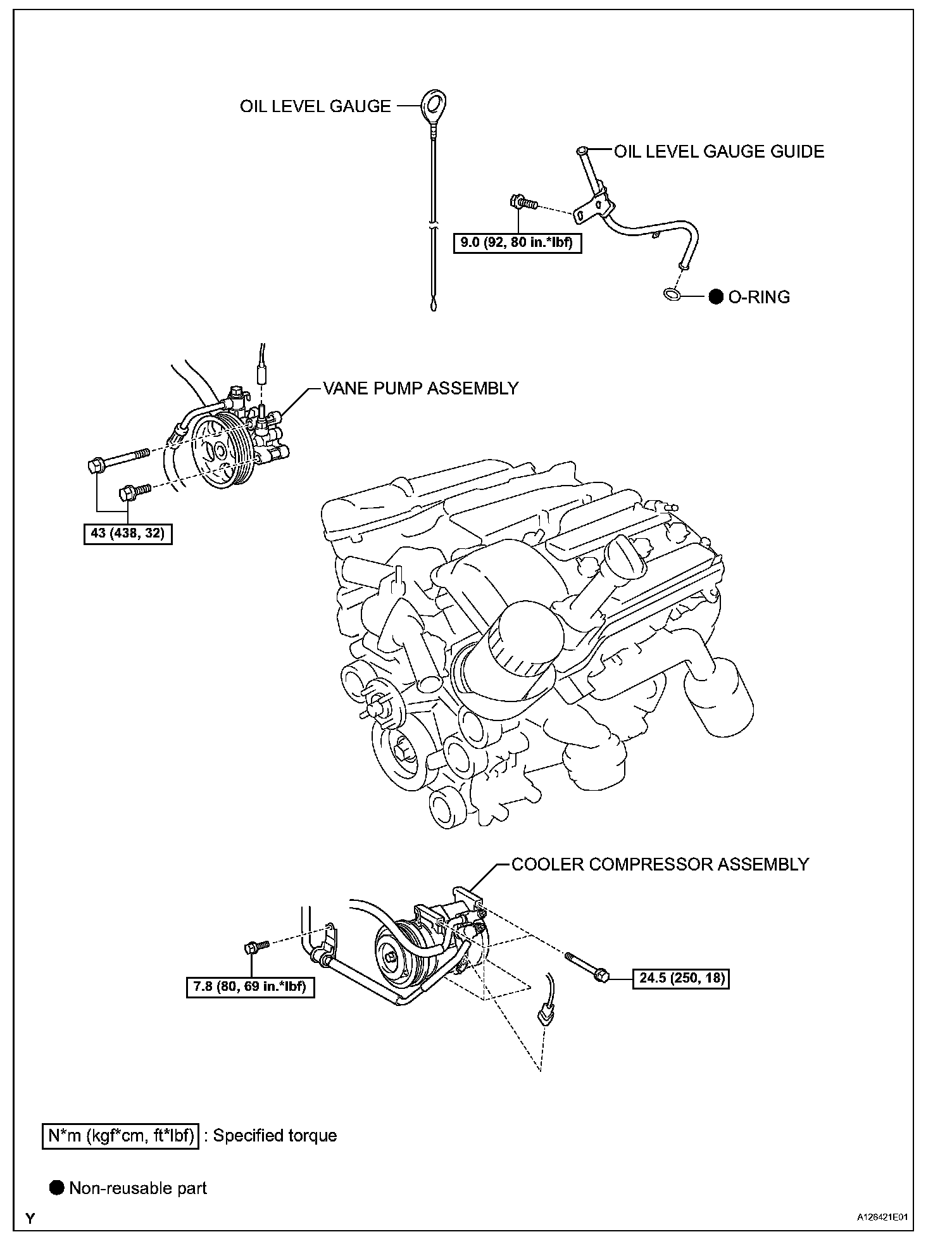
COMPONENTS (Part 4):
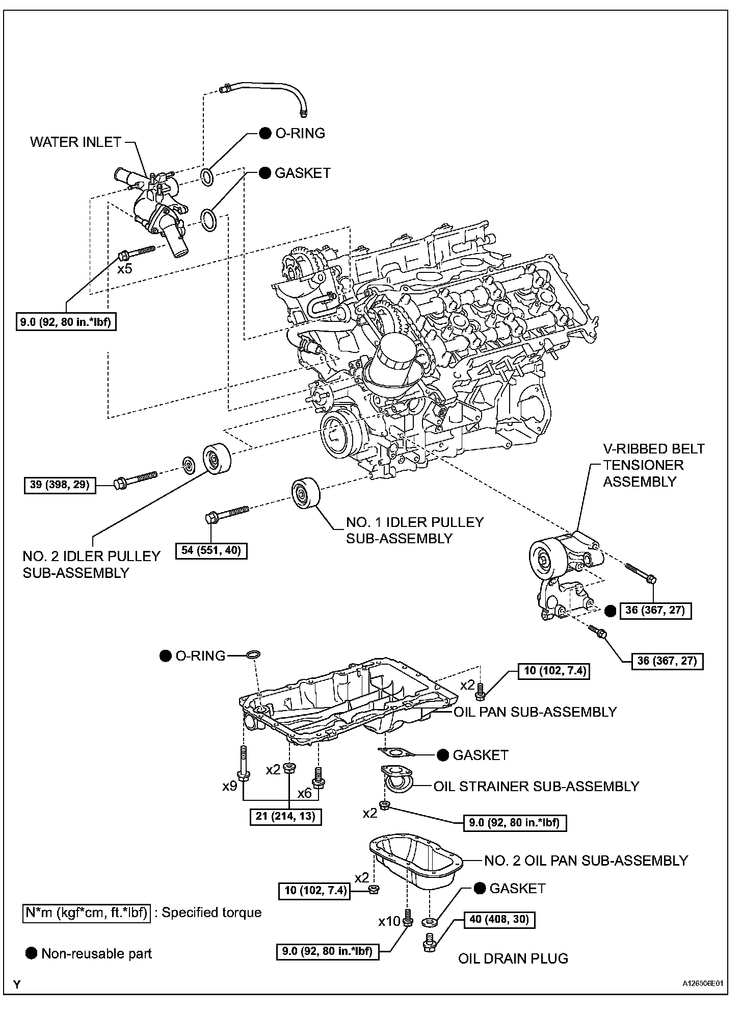
COMPONENTS (Part 5):
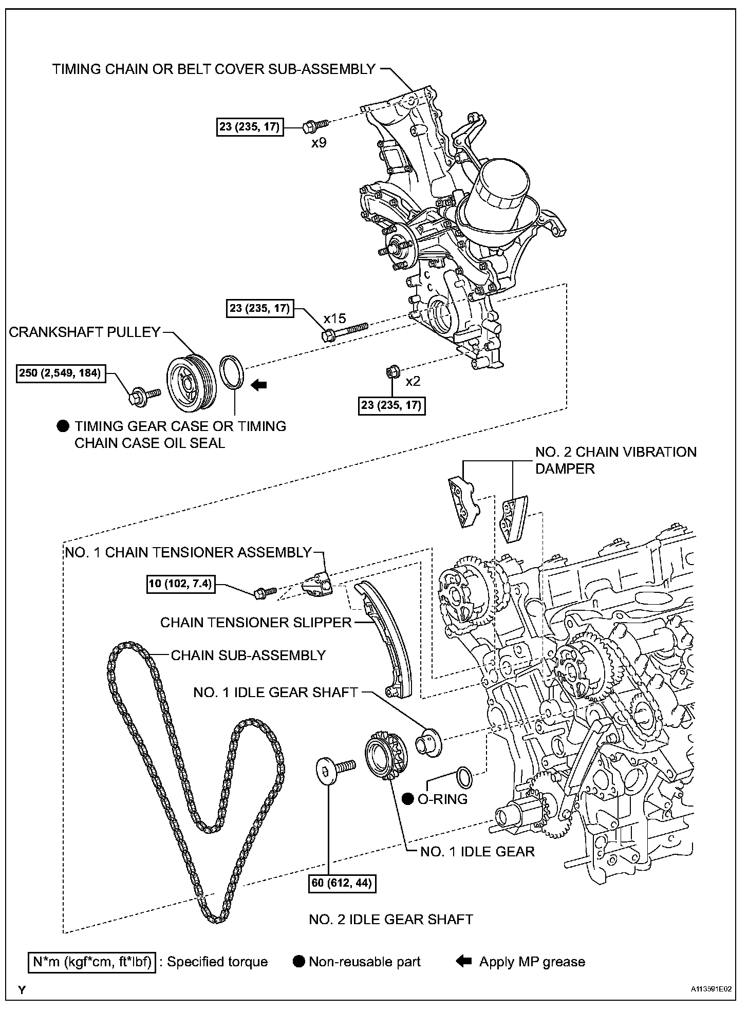
REMOVAL
1. REMOVE BATTERY
2. DRAIN ENGINE COOLANT
3. DRAIN ENGINE OIL
4. REMOVE POWER STEERING LINK ASSEMBLY (for 2WD)
5. REMOVE POWER STEERING LINK ASSEMBLY (for 4WD)
6. REMOVE FRONT DIFFERENTIAL CARRIER ASSEMBLY (for 4WD)
7. REMOVE FAN
8. REMOVE GENERATOR ASSEMBLY
9. SEPARATE COOLER COMPRESSOR ASSEMBLY
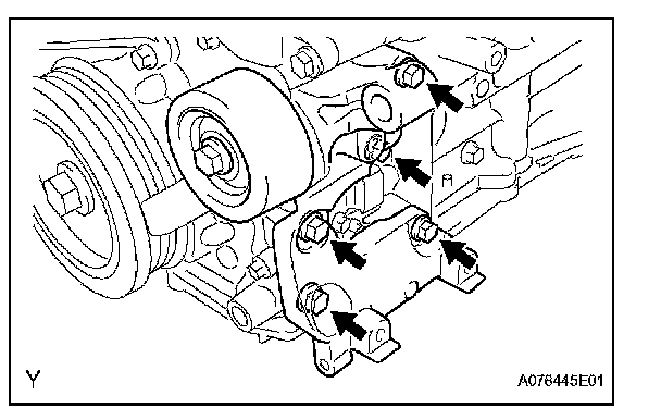
10. REMOVE V-RIBBED BELT TENSIONER ASSEMBLY
(a) Remove the 5 bolts, then remove the V-ribbed belt tensioner.
11. REMOVE OIL LEVEL GAUGE GUIDE
(a) Remove the oil level gauge.
(b) Remove the bolt and pull out the oil level gauge guide.
(c) Remove the O-ring from the oil level gauge guide.
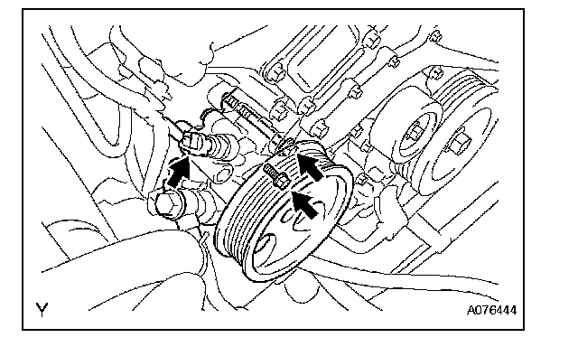
12. SEPARATE VANE PUMP ASSEMBLY
(a) Disconnect the power steering pressure switch connector.
(b) Remove the 2 bolts, then separate the vane pump.
NOTICE: Do not hit the pulley with other parts when separating the vane pump.
HINT: The vane pump is suspended securely.
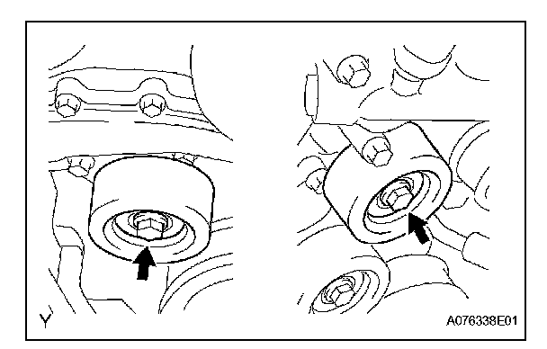
13. REMOVE NO. 2 IDLER PULLEY SUB-ASSEMBLY
(a) Remove the 2 bolts, then remove the No. 2 idler pulleys.
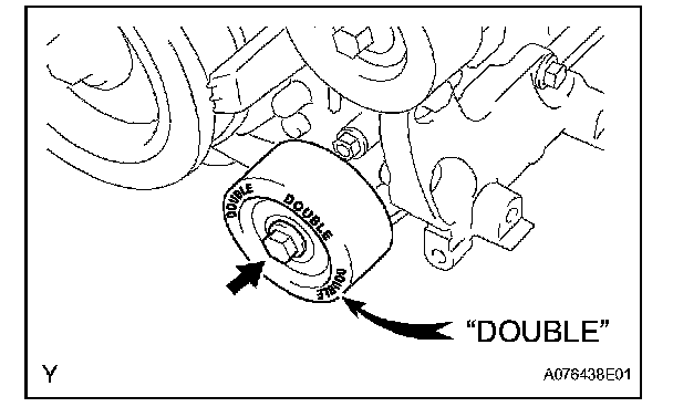
14. REMOVE NO. 1 IDLER PULLEY SUB-ASSEMBLY
(a) Remove the bolt, then remove the No. 1 idler pulley.
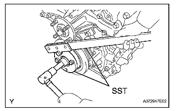
15. REMOVE CRANKSHAFT PULLEY
(a) Using SST, hold the crankshaft pulley and loosen the pulley set bolt.
SST 09213-54015 (91651-60855), 09330-00021
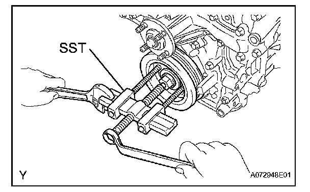
(b) Using the pulley set bolt and SST, remove the crankshaft pulley.
SST 09950-50013 (09951-05010, 09952-05010, 09953-05020, 09954-05030)
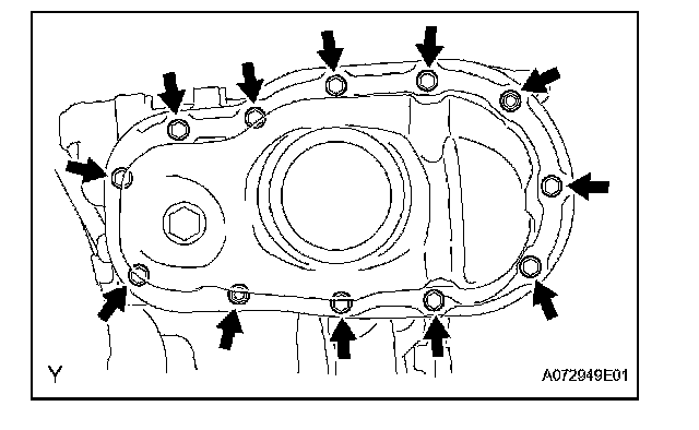
16. REMOVE NO. 2 OIL PAN SUB-ASSEMBLY
(a) Remove the 10 bolts and 2 nuts.
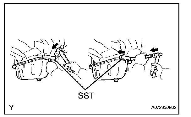
(b) Insert the blade of SST between the oil pan and No. 2 oil pan, cut off applied sealer and remove the No. 2 oil pan.
SST 09032-00100
NOTICE:
^ Be careful not to damage the contact surfaces of the oil pan and No. 2 oil pan.
^ Be careful not to damage the No. 2 oil pan flange.
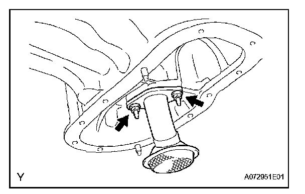
17. REMOVE OIL STRAINER SUB-ASSEMBLY
(a) Remove the 2 nuts, then remove the oil strainer and gasket.
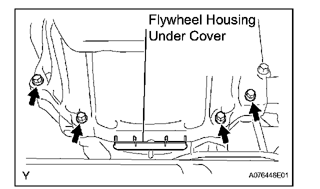
18. REMOVE OIL PAN SUB-ASSEMBLY
(a) Remove the 4 housing bolts.
(b) Remove the flywheel housing under cover.
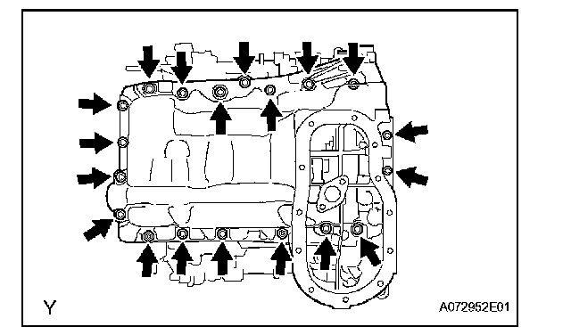
(c) Remove the 17 bolts and 2 nuts.
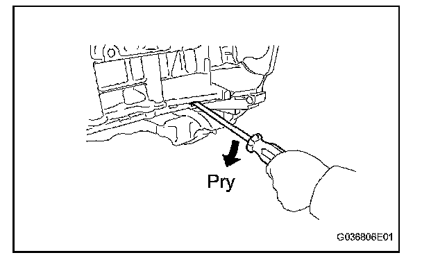
(d) Using a screwdriver, remove the oil pan by prying between the oil pan and cylinder block.
NOTICE: Be careful not to damage the contact surfaces of the cylinder block and oil pan.
(e) Remove the O-ring from the oil pump.
19. REMOVE AIR CLEANER ASSEMBLY
20. REMOVE THROTTLE BODY BRACKET
21. REMOVE OIL BAFFLE PLATE
22. REMOVE NO. 1 SURGE TANK STAY
23. REMOVE NO. 2 SURGE TANK STAY
24. REMOVE INTAKE AIR SURGE TANK
25. REMOVE IGNITION COIL ASSEMBLY
26. REMOVE CAMSHAFT TIMING OIL CONTROL VALVE ASSEMBLY
27. REMOVE VVT SENSOR
28. REMOVE WATER INLET
29. REMOVE CYLINDER HEAD COVER SUB-ASSEMBLY
30. REMOVE CYLINDER HEAD COVER SUB-ASSEMBLY LH
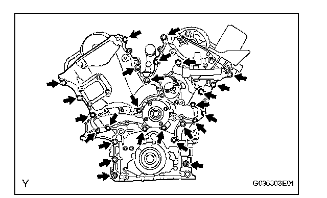
31. REMOVE TIMING CHAIN OR BELT COVER SUB-ASSEMBLY
(a) Remove the 24 bolts and 2 nuts.
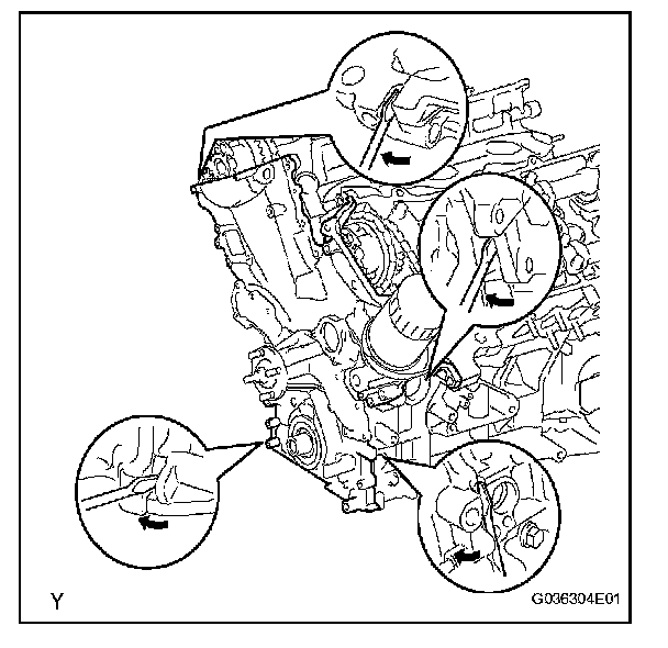
(b) Remove the timing chain cover by prying between the timing chain cover, cylinder head or cylinder block with a screwdriver.
NOTICE: Be careful not to damage the contact surfaces of the timing chain cover, cylinder block and cylinder head.
(c) Remove the O-ring from the LH cylinder head.
32. REMOVE TIMING GEAR CASE OR TIMING CHAIN CASE OIL SEAL
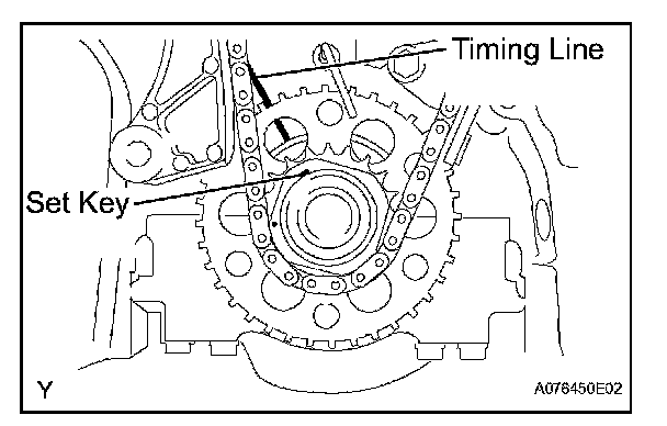
33. SET NO. 1 COMPRESSION TO TDC/COMPRESSION
(a) Using the crankshaft pulley set bolt, turn the crankshaft to align the crankshaft set key with the timing line of the cylinder block.
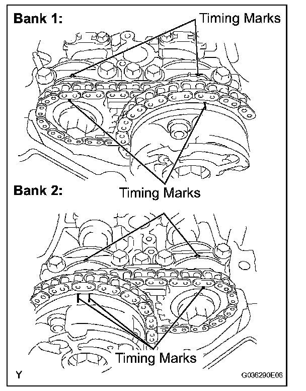
(b) Check that the timing marks of the camshaft timing gears are aligned with the timing marks of the bearing caps as shown in the illustration. If not, turn the crankshaft 1 complete revolution (360°) and align the timing marks as above.
34. REMOVE NO. 1 CHAIN TENSIONER ASSEMBLY
NOTICE:
^ Never rotate the crankshaft with the chain tensioner removed.
^ When rotating the camshaft with the timing chain removed, rotate the crankshaft counterclockwise 40° from the TDC first.
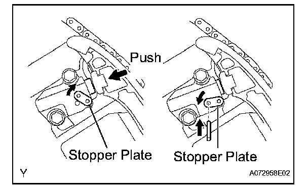
(a) While turning the stopper plate of the tensioner upward, push in the plunger of the chain tensioner as shown in the illustration.
(b) While turning the stopper plate of the tensioner downward, insert a bar of diameter 3.5 mm (0.138) into the holes in the stopper plate and tensioner to fix the stopper plate.
(c) Remove the 2 bolts, then remove the chain tensioner.
35. REMOVE CHAIN TENSIONER SLIPPER
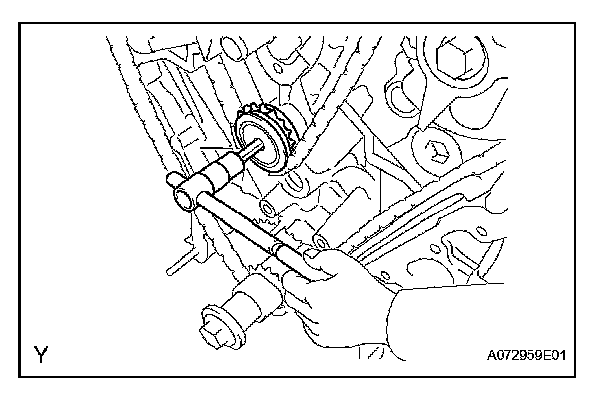
36. REMOVE IDLE SPROCKET ASSEMBLY
(a) Using a 10 mm hexagon wrench, remove the No. 2 idle gear shaft, No. 1 idle gear and No. 1 idle gear shaft.
37. REMOVE NO. 2 CHAIN VIBRATION DAMPER
(a) Remove the 2 No. 2 chain vibration dampers.
38. REMOVE CHAIN SUB-ASSEMBLY
INSTALLATION
1. INSTALL CHAIN TENSIONER SLIPPER
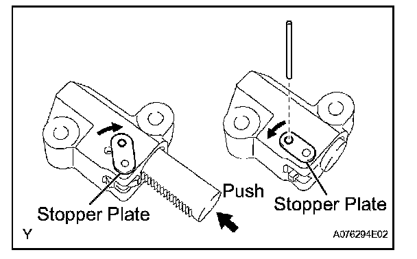
2. INSTALL NO. 1 CHAIN TENSIONER ASSEMBLY
(a) While turning the stopper plate of the tensioner clockwise, push in the plunger of the tensioner as shown in the illustration.
(b) While turning the stopper plate of the tensioner counterclockwise, insert a bar of diameter 35 mm (0.138 in.) into the holes in the stopper plate and tensioner to fix the stopper plate.
(c) Install the chain tensioner with the 2 bolts.
Torque: 10 N*m (102 kgf*cm, 7.4 ft.*lbf.)

3. INSTALL CHAIN SUB-ASSEMBLY
(a) Set the No. 1 cylinder to TDC/compression.
(1) Align the timing marks of the camshaft timing gears and bearing caps.

(2) Using the crankshaft pulley set bolt, turn the crankshaft to align the crankshaft set key with the timing line of the cylinder block.

(b) Align the yellow mark link with the timing mark of the crankshaft timing link.

(c) Align the orange mark links with the timing marks of the camshaft timing gears, and install the chain.
4. INSTALL NO. 2 CHAIN VIBRATION DAMPER
(a) Install the 2 No. 2 chain vibration dampers.
5. INSTALL IDLE SPROCKET ASSEMBLY
(a) Apply a light coat of engine oil to rotating surface of the No. 1 idle gear shaft.
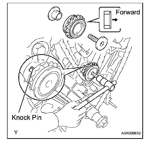
(b) Temporarily install the No. 1 idle gear shaft together with the No. 2 idle gear shaft with the knock pin of the No. 1 idle gear shaft and the knock pin groove of the cylinder block are aligned.
NOTICE: Orient the idle gear shafts correctly.
(c) Using a 10 mm hexagon wrench, tighten the No. 2 idle gear shaft.
Torque: 60 N*m (612 kgf*cm, 44 ft.*lbf.)
(d) Remove the bar from the chain tensioner.
6. INSTALL TIMING GEAR CASE OR TIMING CHAIN CASE OIL SEAL
7. INSTALL TIMING CHAIN OR BELT COVER SUB-ASSEMBLY
(a) Remove any old packing (FIPG) material.
HINT: Do not drop any oil on the contact surfaces of the timing chain cover, cylinder head and cylinder block.
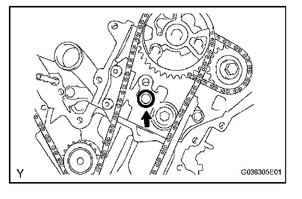
(b) Install a new O-ring onto the bank 2 cylinder head as shown in the illustration.
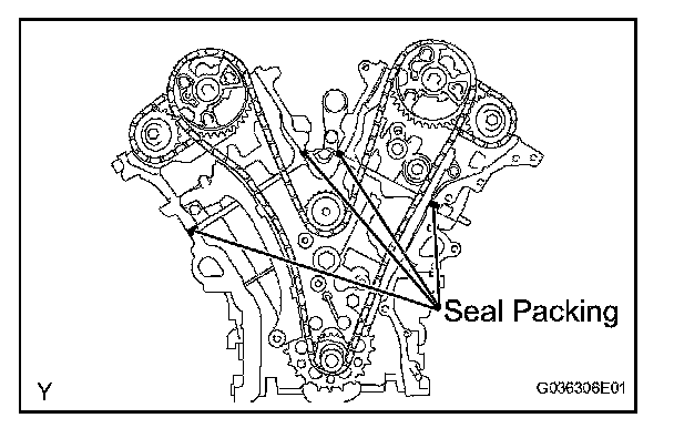
(c) Apply continuous beads of seal packing (diameter 3 to 4 mm (0.12 to 0.16 in.)) to the 4 locations shown in the illustration.
Seal packing: Toyota Genuine Seal Packing Black, Three Bond 1207B or the equivalent
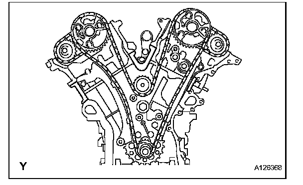
(d) Keep the seal surface between the cylinder block and the cylinder head shown in the illustration free of oil before installing the chain cover.
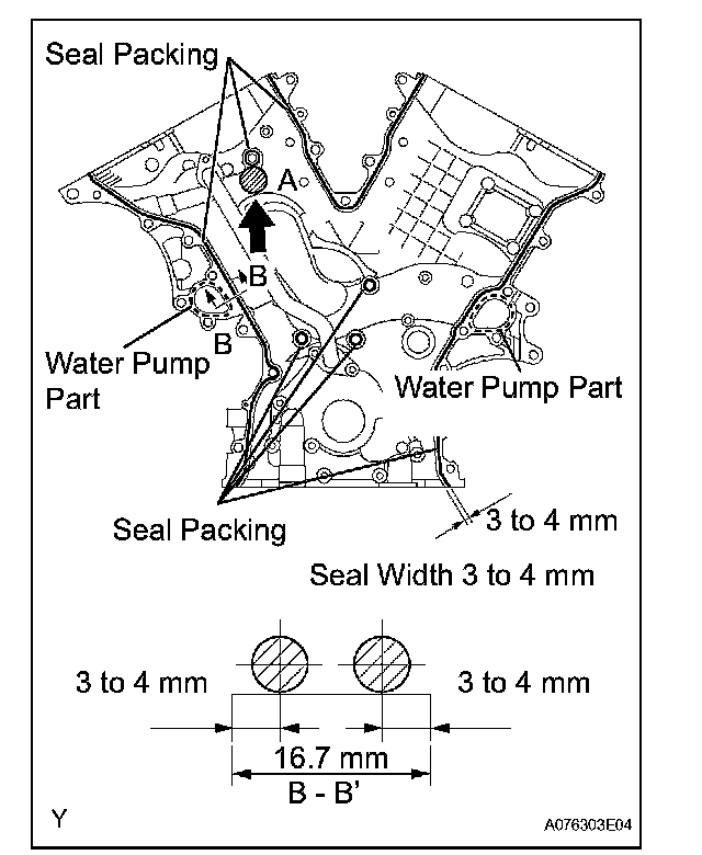
(e) Apply continuous beads of seal packing (diameter 3 to 4 mm (0.12 to 0.16 in.)) to the timing chain cover as shown in the illustration.
Seal packing:
Water pump part: Toyota Genuine Seal Packing 1282B, Three Bond 1282B or the equivalent
Other parts: Toyota Genuine Seal Packing Black, Three Bond 1207B or the equivalent
NOTICE:
^ Install the timing chain cover within 3 minutes of applying the seal packing. The timing chain cover bolts and nuts must be tightened within 15 minutes of the installation. Otherwise the seal packing must be removed and reapplied.
^ Do not apply seal packing to portion A shown in the illustration.
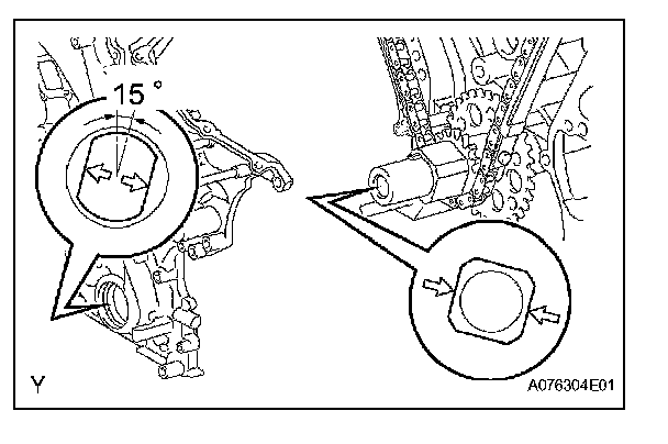
(f) Align the key way of the oil pump drive rotor with the rectangular portion of the crankshaft timing gear, and slide the timing chain cover into place.
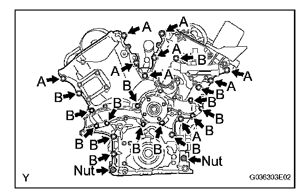
(g) Install the timing chain cover with the 24 bolts and 2 nuts. Tighten the bolts and nuts uniformly in several steps.
Torque: 23 N*m (235 kgf*cm, 17 ft.*lbf.)
NOTICE: Pay attention not to wrap the chain and slipper over the timing chain cover seal line.
Each bolt length is as follows

8. INSTALL CYLINDER HEAD COVER SUB-ASSEMBLY LH
9. INSTALL CYLINDER HEAD COVER SUB-ASSEMBLY
10. INSTALL WATER INLET
11. INSTALL VVT SENSOR
12. INSTALL CAMSHAFT TIMING OIL CONTROL VALVE ASSEMBLY
13. INSTALL IGNITION COIL ASSEMBLY
14. INSTALL INTAKE AIR SURGE TANK
15. INSTALL NO. 2 SURGE TANK STAY
16. INSTALL NO. 1 SURGE TANK STAY
17. INSTALL OIL BAFFLE PLATE
18. INSTALL THROTTLE BODY BRACKET
19. INSTALL AIR CLEANER ASSEMBLY
20. INSTALL OIL PAN SUB-ASSEMBLY
(a) Remove any old packing (FIPG) material.
HINT: Do not drop any oil on the contact surfaces of the cylinder block, rear oil seal and oil pan.
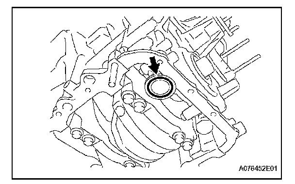
(b) Install a new O-ring onto the oil pump.
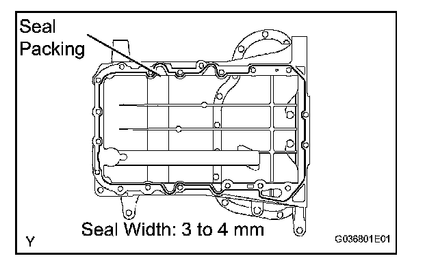
(c) Apply a continuous bead of seal packing (diameter 3 to 4 mm (0.12 to 0.16 in.)) to the oil pan as shown in the illustration.
Seal packing: Toyota Genuine Seal Packing Black, Three Bond 1207B or the equivalent
NOTICE: Install the oil pan within 3 minutes of applying the seal packing. Tighten the oil pan bolts and nuts within 15 minutes of installing the oil pan. Otherwise, the seal packing must be removed and reapplied.
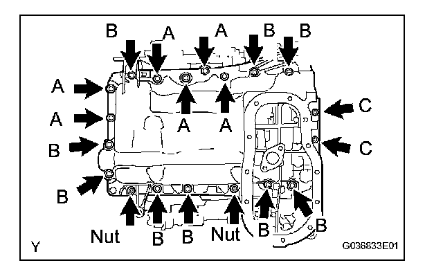
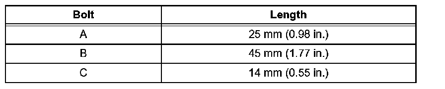
(d) Install the oil pan with the 17 bolts and 2 nuts, and tighten the bolts and nuts uniformly in several steps.
Torque: 10 mm (0.39 in.) head
10 N*m (102 kgf*cm, 7.4 ft.*lbf.)
12 mm (0.47 in.) head
21 N*m (214 kgf*cm, 16 ft.*lbf.)
Nut 21 N*m (1,214 kgf*cm, 16 ft.*lbf.)
HINT: Each bolt length is as follows:
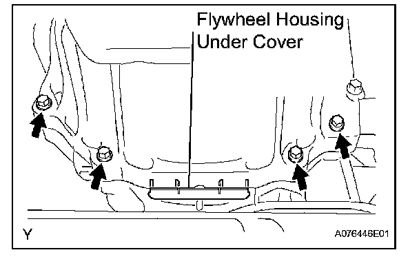
(e) Install the 4 housing bolts.
Torque: 37 N*m (377 kgf*cm, 27 ft.*lbf.)
(f) Install the flywheel housing under cover.
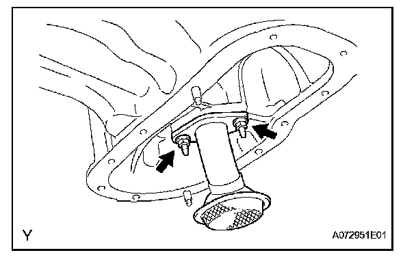
21. INSTALL OIL STRAINER SUB-ASSEMBLY
(a) Install a new gasket and the oil strainer with the 2 nuts.
Torque: 9.0 N*m (92 kgf*cm, 80 in.*lbf.)
22. INSTALL NO. 2 OIL PAN SUB-ASSEMBLY
(a) Remove any old packing (FIPG) material.
HINT: Do not drop any oil on the contact surfaces of the oil pan and No. 2 oil pan.
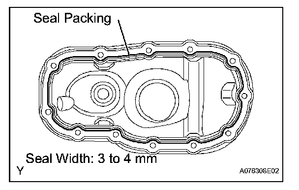
(b) Apply a continuous bead of seal packing (diameter 3 to 4 mm (0.12 to 0.16 in.)) as shown in the illustration.
Seal packing: Toyota Genuine Seal Packing Black, Three Bond 1207B or the equivalent
NOTICE: Install the No. 2 oil pan within 3 minutes of applying the seal packing. Tighten the No. 2 oil pan bolts and nuts within 15 minutes of installing the No. 2 oil pan. Otherwise, the seal packing must be removed and reapplied.
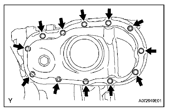
(c) Install the No. 2 oil pan with the 10 bolts and 2 nuts. Tighten the bolts and nuts uniformly in several steps.
Torque: Bolt 9.0 N*m (92 kgf*cm, 80 in.*lbf.)
Nut 10 N*m (102 kgf*cm, 7.4 in.*lbf.)
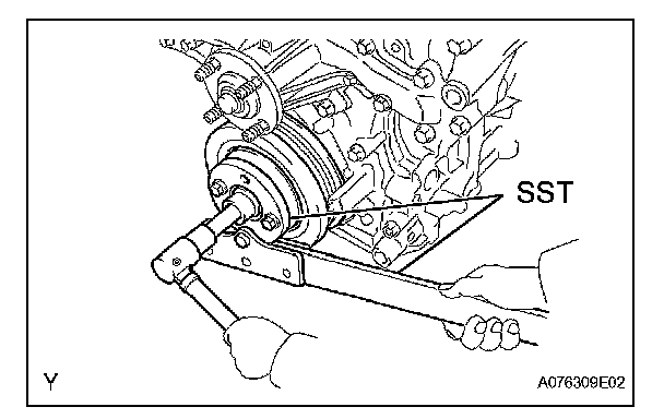
23. INSTALL CRANKSHAFT PULLEY
(a) Using SST, install the pulley set bolt.
SST 09213-54015 (91651-60855), 09330-00021
Torque: 250 N*m (2,549 kgf*cm, 184 ft.*lbf.)
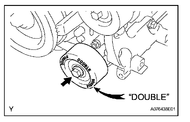
24. INSTALL NO. 1 IDLER PULLEY SUB-ASSEMBLY
(a) Install the idler pulley with the bolt.
Torque: 39 N*m (398 kgf*cm, 29 ft.*lbf.)
HINT: DOUBLE is marked on the No. 1 idler pulley to distinguish it from the No. 2 idler pulley.
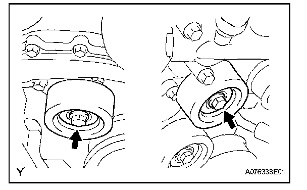
25. INSTALL NO. 2 IDLER PULLEY SUB-ASSEMBLY
(a) Install the 2 No. 2 idler pulleys with the 2 bolts.
Torque: 54 N*m (551 kgf*cm, 40 ft.*lbf.)
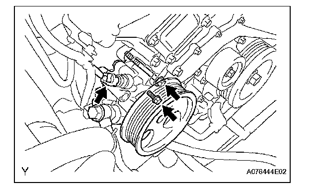
26. INSTALL VANE PUMP ASSEMBLY
(a) Install the vane pump with the 2 bolts.
Torque: 43 N*m (438 kgf*cm, 32 ft.*lbf.)
NOTICE: Do not hit the pulley with other parts when installing the vane pump.
(b) Connect the power steering pressure switch connector.
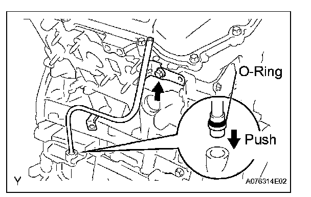
27. INSTALL OIL LEVEL GAUGE GUIDE
(a) Install a new O-ring onto the oil level gauge guide.
(b) Apply a light coat of engine oil to the O-ring.
(c) Push the oil level gauge guide end into the guide hole in the oil pan.
(d) Install the oil level gauge guide with the bolt.
Torque: 9.0 N*m (92 kgf*cm, 80 in.*lbf.)
(e) Install the oil level gauge guide.
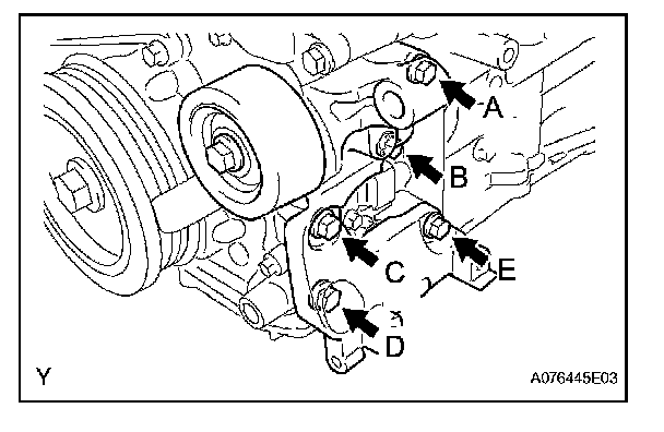
28. INSTALL V-RIBBED BELT TENSIONER ASSEMBLY
NOTICE: The bolt in position A is not reusable.
HINT: Each bolt length is as follows:

(a) Use a new bolt in position A.
(b) Finger-tighten the bolts in positions A and E and install the bracket.
(c) Tighten the bolts in positions A and E.
Torque: 36 N*m (267 kgf*cm, 27 ft.*lbf.)
(d) Tighten the bolts in positions B, C and D.
Torque: 36 N*m (267 kgf*cm, 27 ft.*lbf.)
29. INSTALL COOLER COMPRESSOR ASSEMBLY
30. INSTALL GENERATOR ASSEMBLY
31. INSTALL FAN
32. INSTALL FRONT DIFFERENTIAL CARRIER ASSEMBLY (for 4WD)
33. INSTALL POWER STEERING LINK ASSEMBLY (for 2WD)
34. INSTALL POWER STEERING LINK ASSEMBLY (for 4WD)
35. INSTALL BATTERY
36. ADD ENGINE COOLANT
37. ADD ENGINE OIL
38. ADD POWER STEERING FLUID
39. BLEED POWER STEERING FLUID
40. ADD DIFFERENTIAL OIL (for 4WD)
41. INSPECT DIFFERENTIAL OIL (for 4WD)
42. CHECK FOR ENGINE COOLANT LEAKAGE
43. CHECK FOR ENGINE OIL LEAKAGE
44. CHECK FOR POWER STEERING FLUID LEAKAGE
45. CHECK FOR DIFFERENTIAL OIL LEAKAGE
46. INSPECT AND ADJUST FRONT WHEEL ALIGNMENT