Front
FRONT BRAKECOMPONENTS (Part 1):
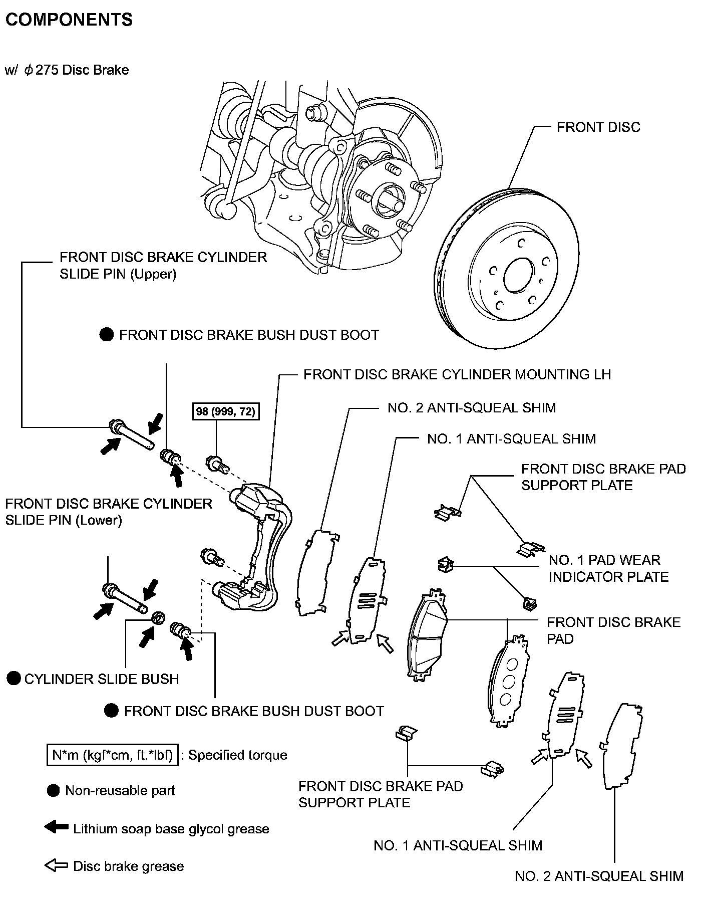
COMPONENTS (Part 2):
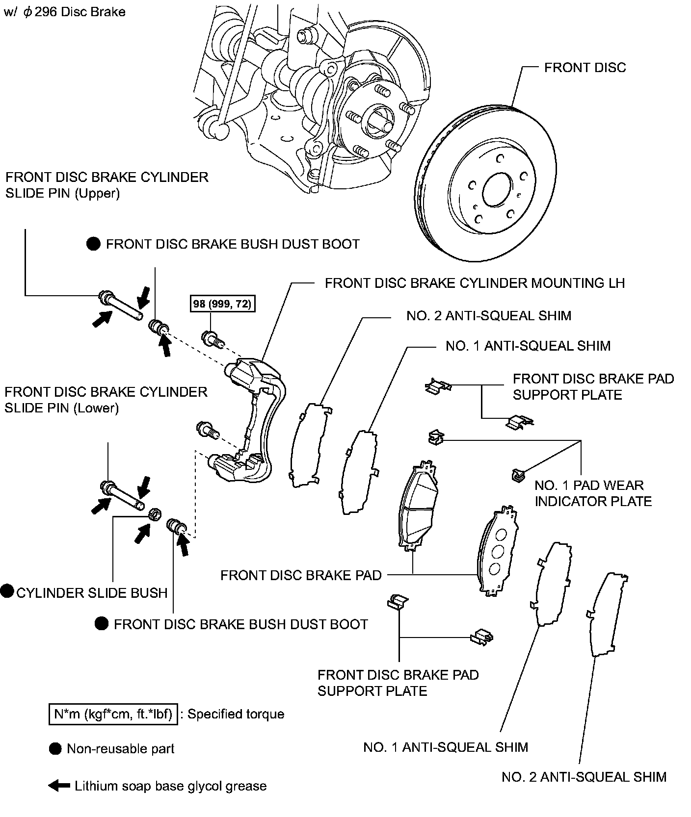
COMPONENTS (Part 3):
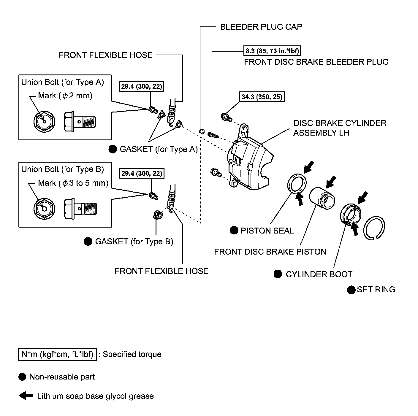
REMOVAL
HINT:
^ Use the same procedures for the LH side and RH side.
^ The procedures listed below are for the LH side.
1. REMOVE FRONT WHEEL
2. DRAIN BRAKE FLUID
NOTICE: Wash off brake fluid immediately if it comes in contact with any painted surface.
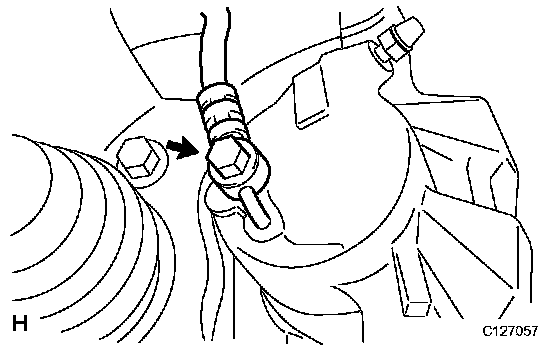
3. DISCONNECT FRONT FLEXIBLE HOSE
(a) Remove the union bolt and gasket(s).
(b) Disconnect the flexible hose from the brake cylinder.
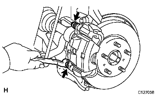
4. REMOVE DISC BRAKE CYLINDER ASSEMBLY LH
(a) Remove the 2 bolts and cylinder.
INSTALLATION
HINT:
^ Use the same procedures for the LH side and RH side.
^ The procedures listed below are for the LH side.
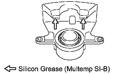
1. INSTALL DISC BRAKE CYLINDER ASSEMBLY LH
(a) Apply silicon grease (Multemp SI-B) on the contact surfaces of the cylinder parts indicated by the arrows.
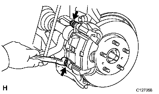
(b) Install the cylinder with the 2 bolts.
Torque: 34.3 Nm (350 kgf-cm, 25 ft. lbs.)
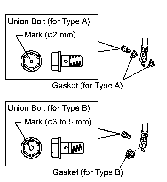
2. CONNECT FRONT FLEXIBLE HOSE
NOTICE: The gasket and union bolt must be used as a set, as shown in the illustration.
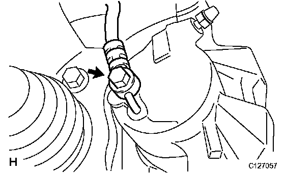
(a) Connect the flexible hose with new gasket(s) and the union bolt.
Torque: 29.4 Nm (300 kgf-cm, 22 ft. lbs.)
HINT: Install the flexible hose lock securely in the lock hole in the cylinder.
3. FILL RESERVOIR WITH BRAKE FLUID
4. BLEED AIR FROM BRAKE MASTER CYLINDER
5. BLEED AIR FROM BRAKE LINE
6. BLEED AIR FROM ABS AND TRACTION ACTUATOR ASSEMBLY
7. CHECK BRAKE FLUID LEVEL IN RESERVOIR
8. INSPECT FOR FLUID LEAK
9. INSTALL FRONT WHEEL
Torque: 103 Nm (1,050 kgf-cm, 76 ft. lbs.)