Installation
ENGINE ASSEMBLYCOMPONENTS (Part 1):
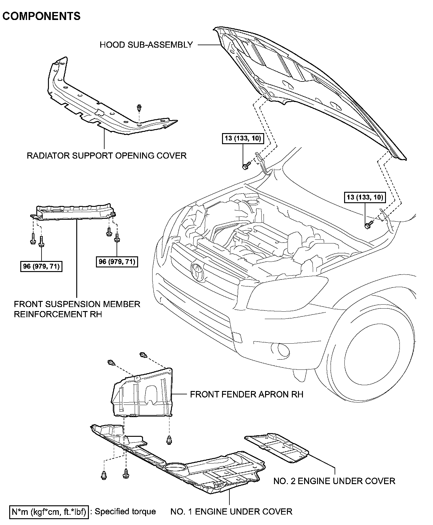
COMPONENTS (Part 2):
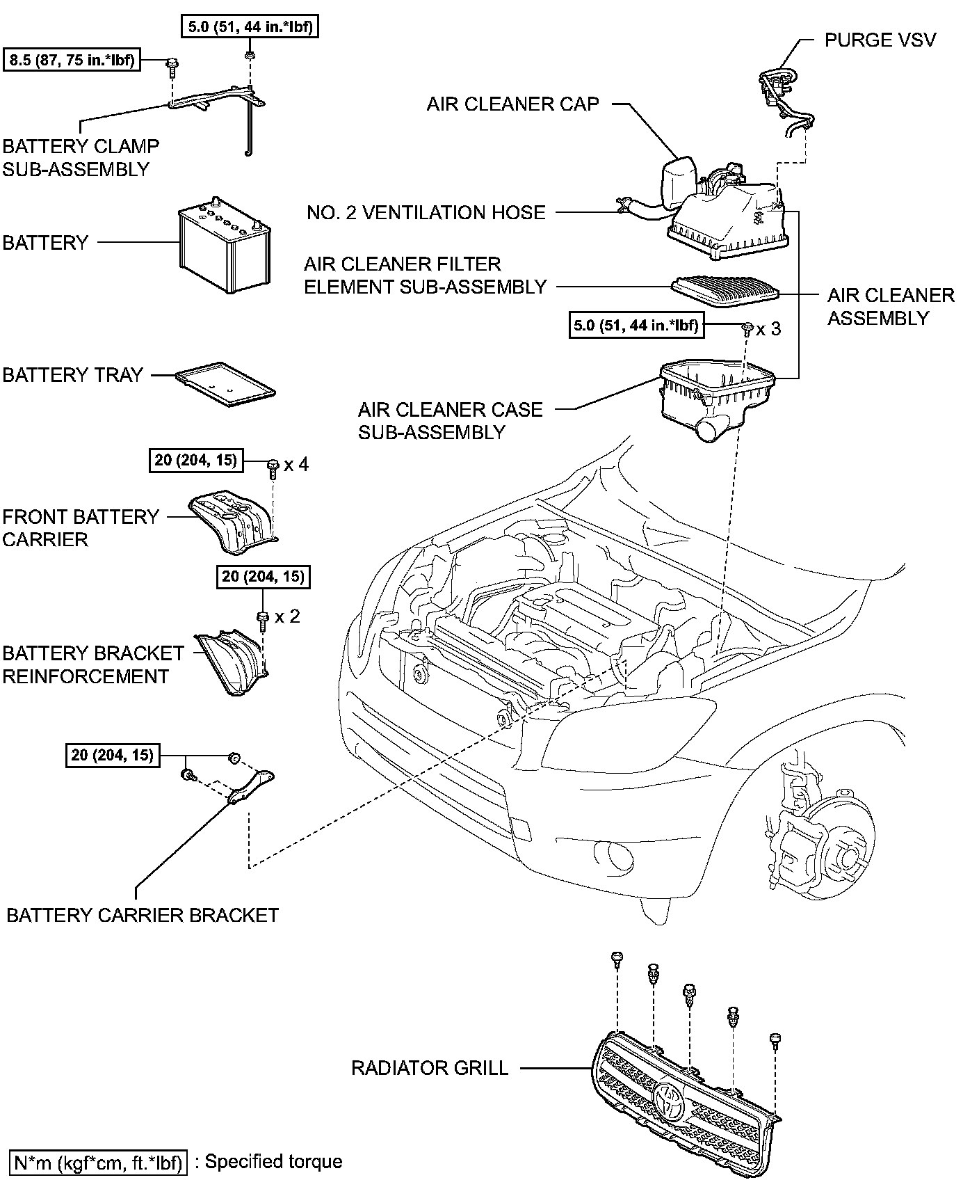
COMPONENTS (Part 3):
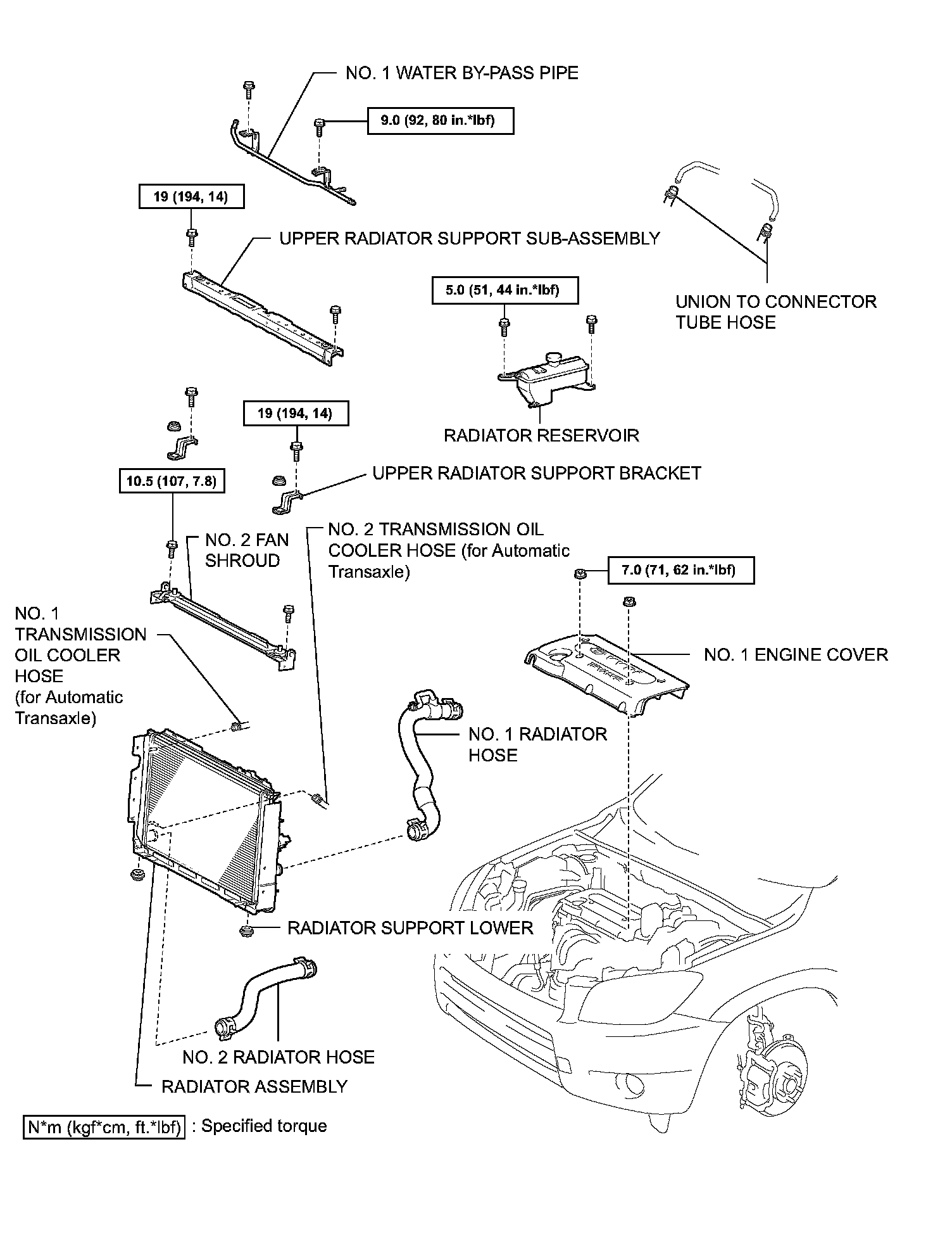
COMPONENTS (Part 4):
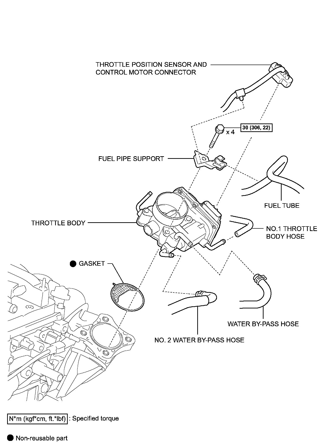
COMPONENTS (Part 5):
COMPONENTS (Part 6):
COMPONENTS (Part 7):
COMPONENTS (Part 8):
COMPONENTS (Part 9):
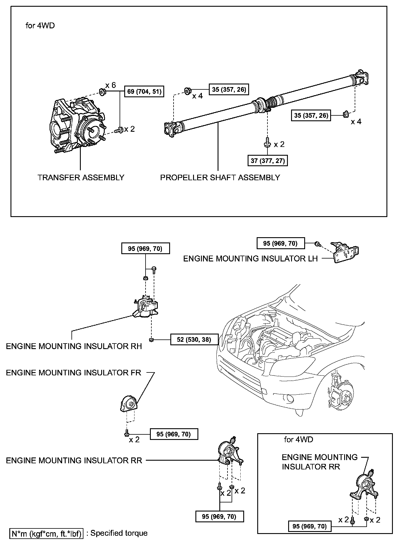
COMPONENTS (Part 10):
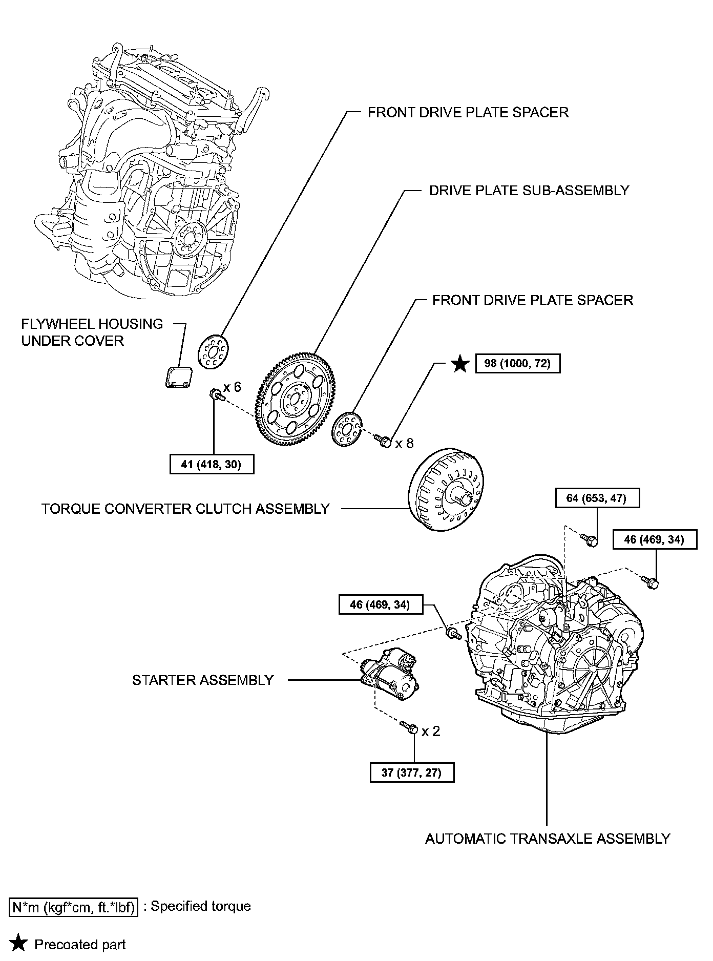
INSTALLATION
1. INSTALL DRIVE PLATE SUB-ASSEMBLY
(a) Clean the 8 bolts and 8 bolt holes.
(b) Apply adhesive to 2 or 3 threads of the 8 bolts.
Adhesive: Toyota Genuine Adhesive 1342, Three Bond 1342 or equivalent
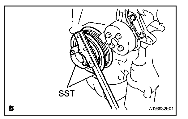
(c) Using SST, hold the crankshaft.
SST 09213-54015 (91651-60855), 09330-00021
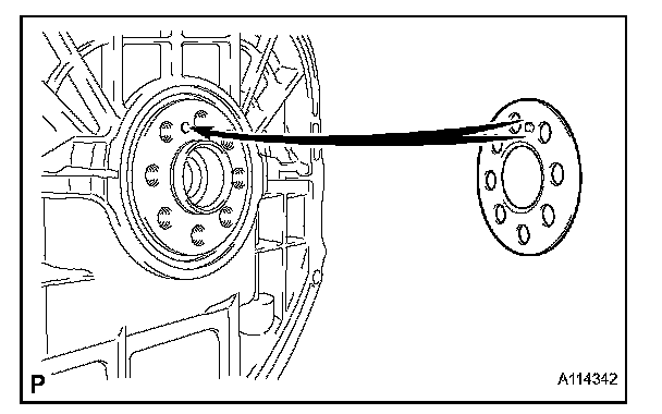
(d) Install the front spacer.
HINT: Align the pin of the front spacer with the pin hole of the crankshaft.
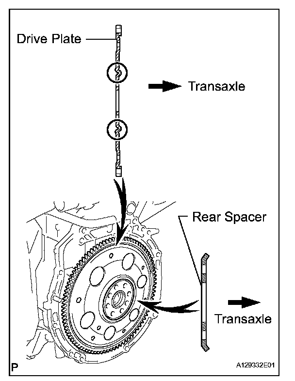
(e) Install the drive plate and rear spacer onto the crankshaft.

(f) Using several steps, uniformly install and tighten the 8 bolts in the sequence shown in the illustration.
Torque: 98 Nm (1,000 kgf-cm, 72 ft. lbs.)
2. INSTALL TORQUE CONVERTER CLUTCH ASSEMBLY
(a) Install the torque converter clutch for U241E (2WD).
(b) Install the torque converter clutch for U140F (4WD).
3. INSTALL AUTOMATIC TRANSAXLE ASSEMBLY
(a) Install the automatic transaxle for U241E (2WD).
(b) Install the automatic transaxle for U140F (4WD).
4. INSTALL STARTER ASSEMBLY
5. INSTALL TRANSFER ASSEMBLY (for 4WD)
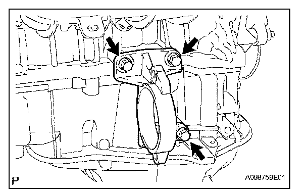
6. INSTALL DRIVE SHAFT BEARING BRACKET (for 2WD)
(a) Install the bracket with the 3 bolts.
Torque: 64 Nm (653 kgf-cm, 47 ft. lbs.)
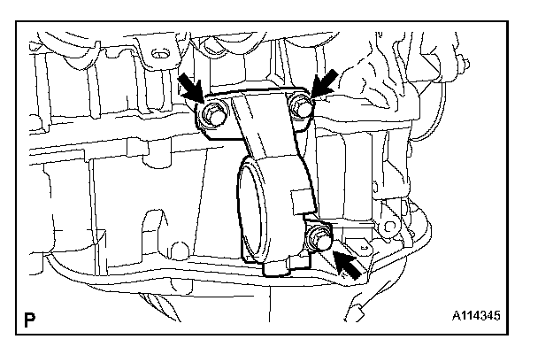
7. INSTALL DRIVE SHAFT BEARING BRACKET (for 4WD)
(a) Install the bracket with the 3 bolts.
Torque: 64 Nm (653 kgf-cm, 47 ft. lbs.)
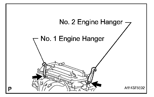
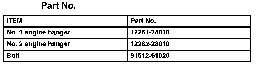
8. INSTALL ENGINE HANGER
(a) Install the No. 1 and No. 2 engine hangers.
Torque: 38 Nm (387 kgf-cm, 28 ft. lbs.)
Part No.:
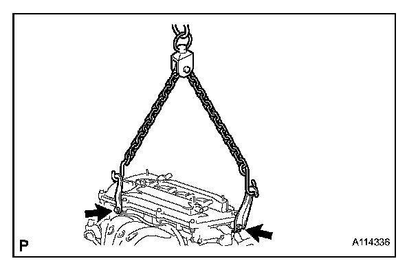
(b) Attach the sling device and the engine with the chain block.
9. INSTALL ENGINE ASSEMBLY WITH TRANSAXLE
(a) Lift the engine assembly (with transaxle) with the chain block.
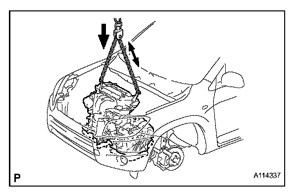
(b) Lower the engine out of the vehicle slowly and carefully.
NOTICE: Make sure the engine is clear of all wiring, hoses and cables.

10. INSTALL ENGINE MOUNTING INSULATOR LH
(a) Install the engine mounting insulator LH with the 4 bolts.
Torque: 95 Nm (969 kgf-cm, 70 ft. lbs.)
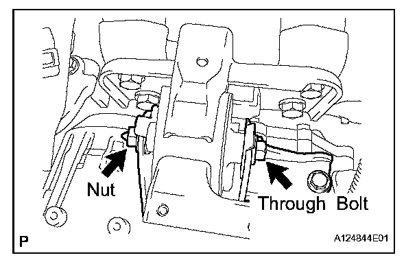
(b) Install the engine mounting insulator LH with the through bolt and nut.
HINT: Install the through bolt by tightening the nut.
Torque: 56 Nm (571 kgf-cm, 41 ft. lbs.)
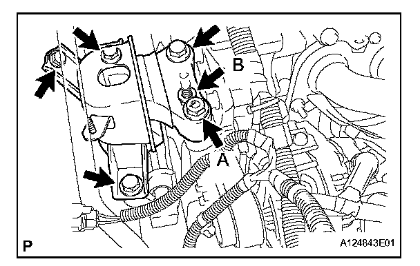
11. INSTALL ENGINE MOUNTING INSULATOR RH
(a) Install the engine mounting insulator RH with the 2 bolts and 2 nuts.
Torque:
95 Nm (969 kgf-cm, 70 ft. lbs.) for bolt
95 Nm (969 kgf-cm, 70 ft. lbs.) for nut A
52 Nm (530 kgf-cm, 38 ft. lbs.) for nut B
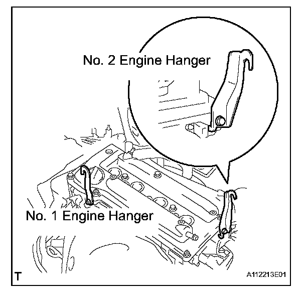
12. REMOVE ENGINE HANGER
(a) Remove the No. 1 and No. 2 engine hangers.
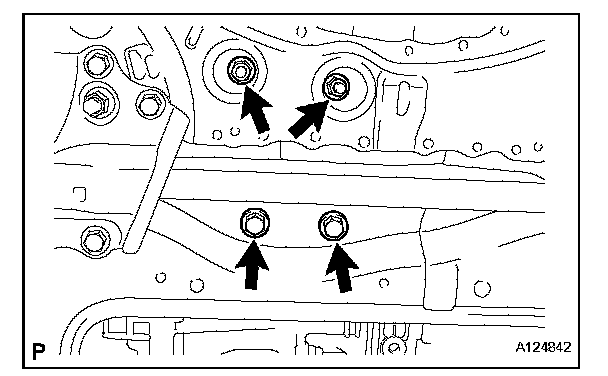
13. INSTALL ENGINE MOUNTING INSULATOR RR
(a) Install the engine mounting insulator RR with the 2 nuts and 2 bolts.
Torque: 95 Nm (969 kgf-cm, 70 ft. lbs.)
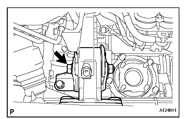
(b) Install the through bolt which is used to secure the rear engine mounting insulator, into the rear engine mounting bracket.
Torque: 95 Nm (969 kgf-cm, 70 ft. lbs.)
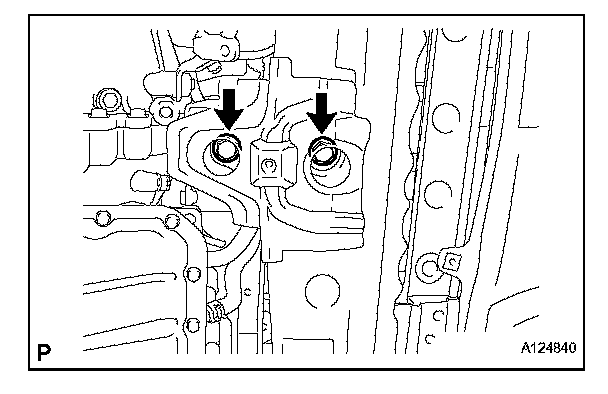
14. INSTALL ENGINE MOUNTING INSULATOR FR
(a) Install the engine mounting insulator FR with the 2 bolts.
Torque: 95 Nm (969 kgf-cm, 70 ft. lbs.)
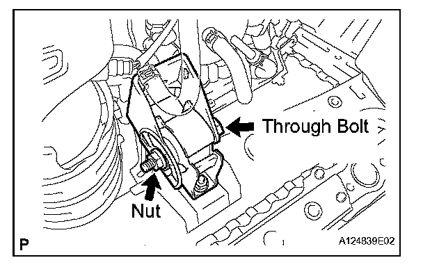
(b) Install the through bolt and nut which is used to secure the front engine mounting bracket FR.
HINT: Install the through bolt by tightening the nut.
Torque: 145 Nm (1,479 kgf-cm, 107 ft. lbs.)
15. INSTALL PROPELLER SHAFT ASSEMBLY (for 4WD)
(a) Install the propeller shaft.
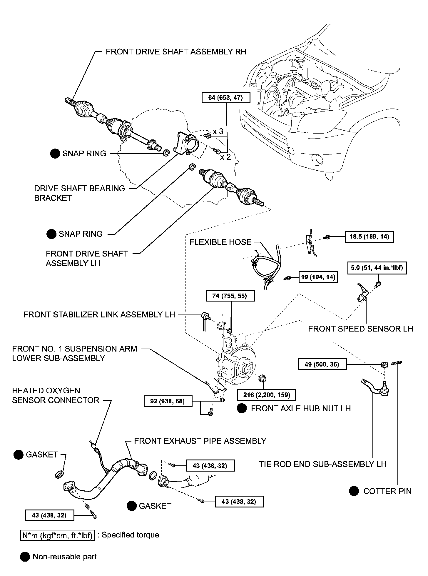
16. INSTALL FRONT DRIVE SHAFT ASSEMBLY
(a) Install the front drive shaft RH (for 2WD).
(b) Install the front drive shaft RH (for 4WD).
17. INSTALL FRONT EXHAUST PIPE
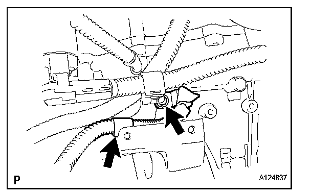
18. CONNECT ENGINE WIRE
(a) Install the ground cable with the bolt located near the starter.
Torque: 13 Nm (133 kgf-cm, 10 ft. lbs.)
(b) Connect the ground cable to the clamp located near the starter.
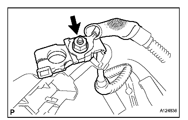
(c) Connect the engine wire to the positive (+) battery terminal with the nut.
Torque: 13 Nm (133 kgf-cm, 10 ft. lbs.)
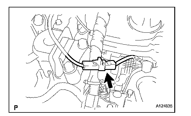
(d) Connect the ground cable connector.
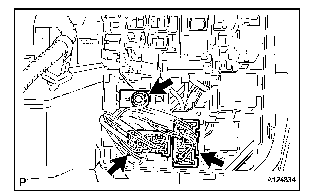
(e) Connect the 2 engine wire connectors and install the nut.
(f) Install the engine room relay block cover.
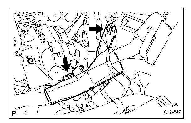
(g) Attach the clamp of the engine wire cover.
(h) Install the engine wire cover to with the bolt.
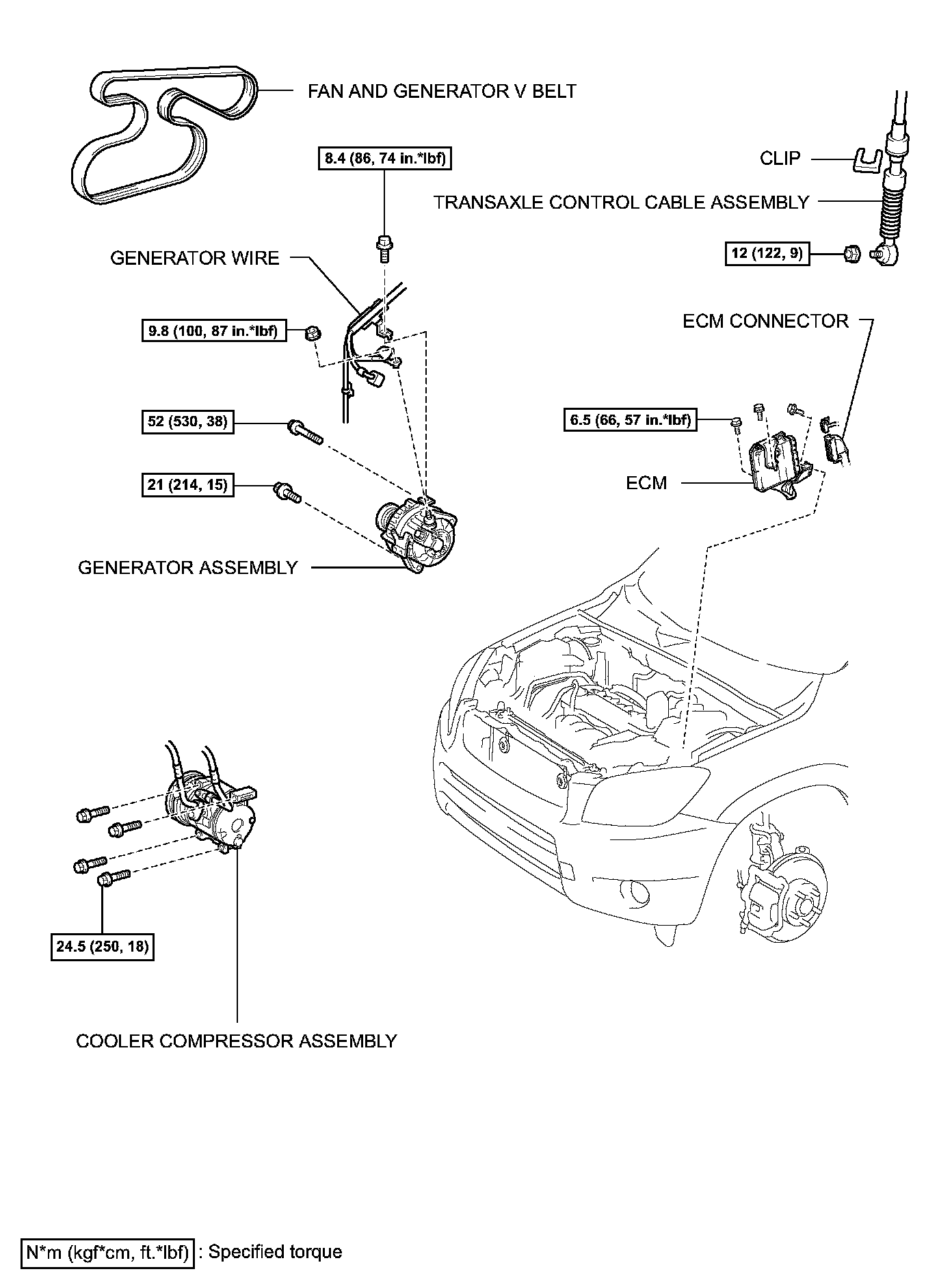
19. INSTALL ECM
20. INSTALL COOLER COMPRESSOR ASSEMBLY
21. INSTALL GENERATOR ASSEMBLY
22. INSTALL FAN AND GENERATOR V BELT
23. INSTALL FRONT SUSPENSION MEMBER REINFORCEMENT RH
24. INSTALL TRANSAXLE CONTROL CABLE ASSEMBLY
(a) Install the transaxle control cable for U241E.
(b) Install the transaxle control cable for U140F.
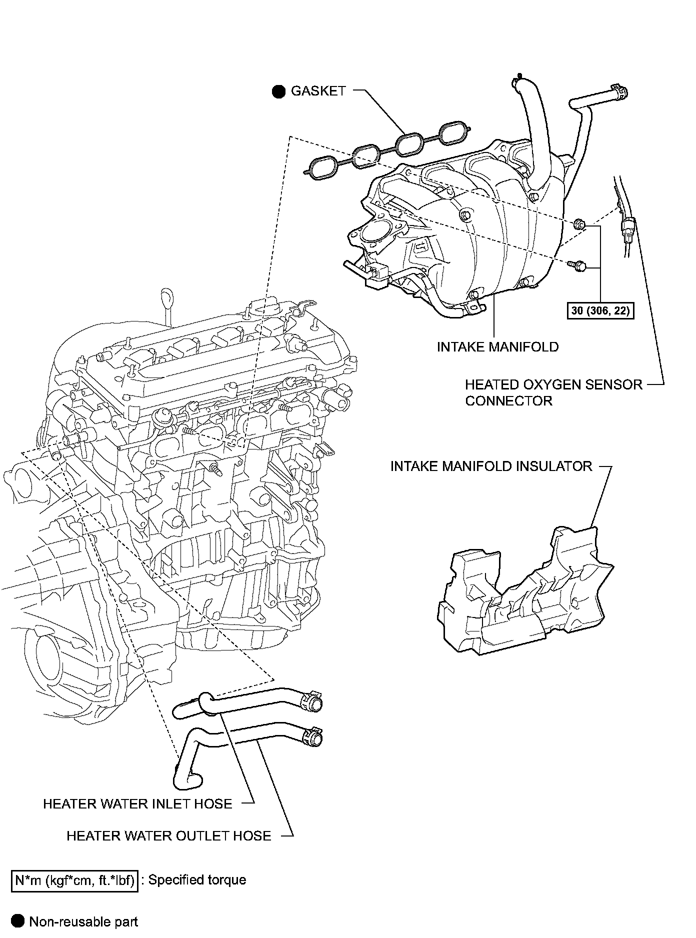
25. INSTALL INTAKE MANIFOLD INSULATOR
26. INSTALL INTAKE MANIFOLD
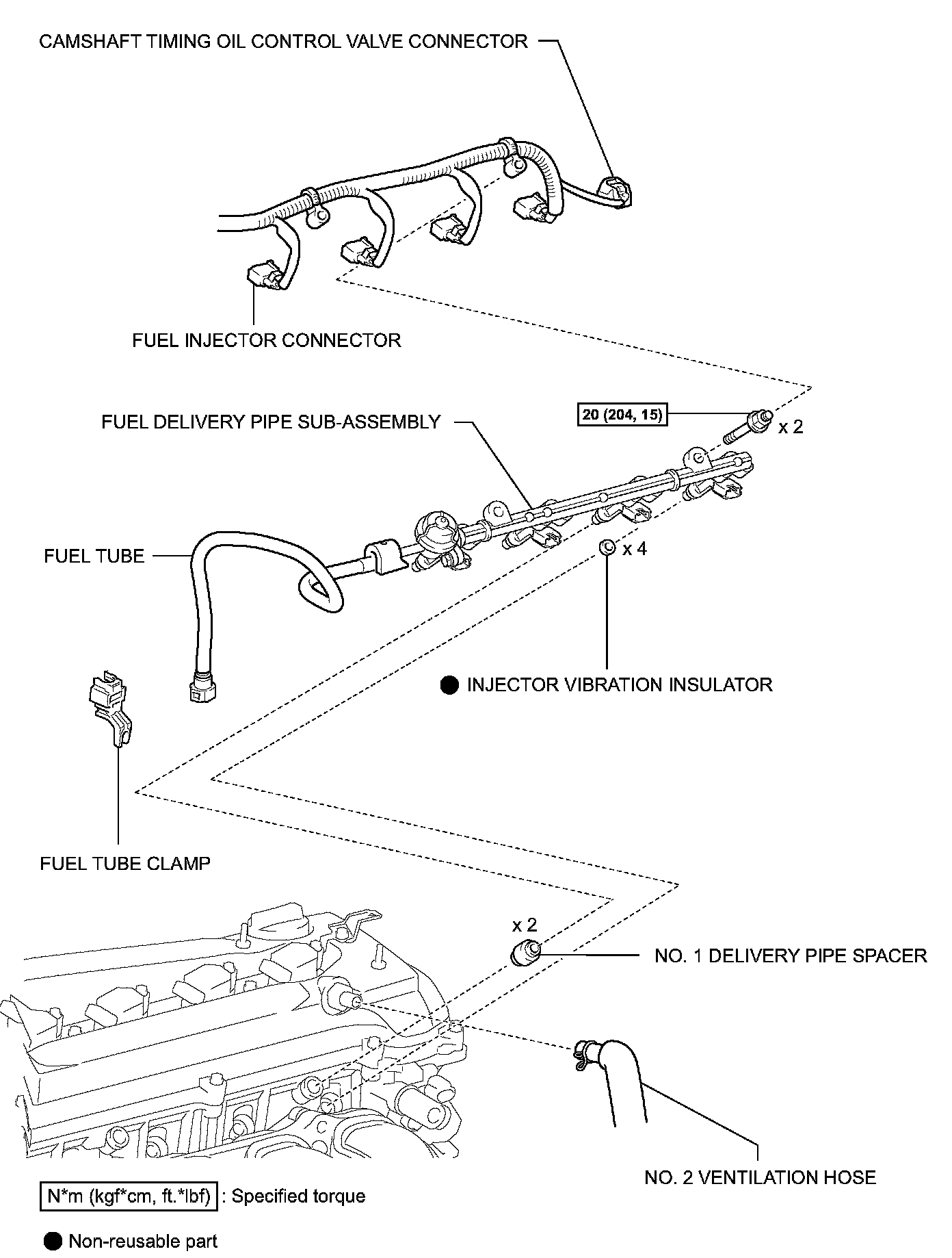
27. INSTALL FUEL DELIVERY PIPE SUB-ASSEMBLY
28. CONNECT NO. 2 VENTILATION HOSE
29. INSTALL THROTTLE BODY ASSEMBLY
30. CONNECT FUEL TUBE
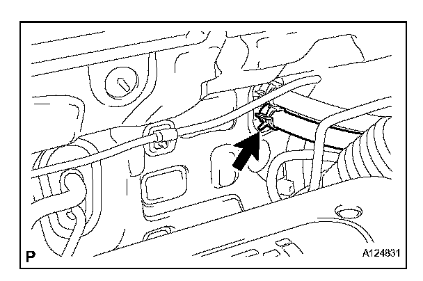
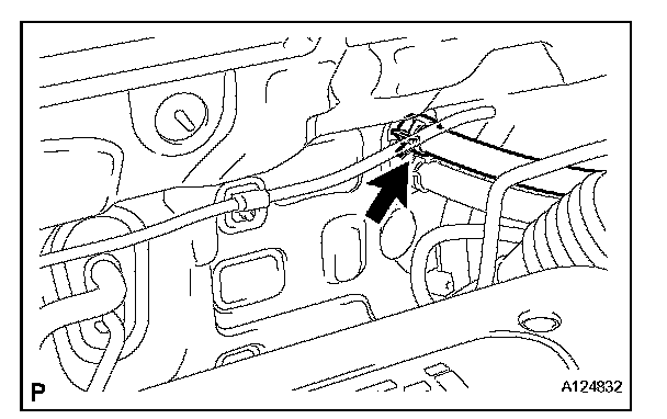
31. CONNECT HEATER WATER OUTLET HOSE
(a) Connect the heater water outlet hose to the air conditioner tube.
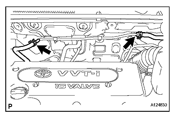
32. CONNECT HEATER WATER INLET HOSE
(a) Connect the heater water inlet hose to the air conditioner tube.
33. CONNECT UNION TO CONNECTOR TUBE HOSE
(a) Connect the 2 union to connector tube hoses to the booster vacuum tube.
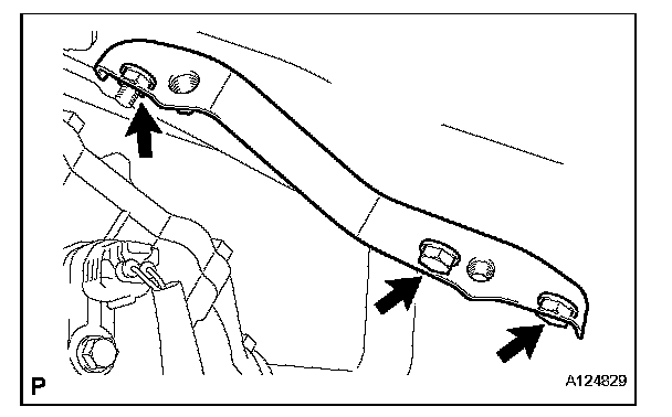
34. INSTALL BATTERY CARRIER BRACKET
(a) Install the battery carrier bracket with the nut and 2 bolts.
Torque: 20 Nm (204 kgf-cm, 15 ft. lbs.)
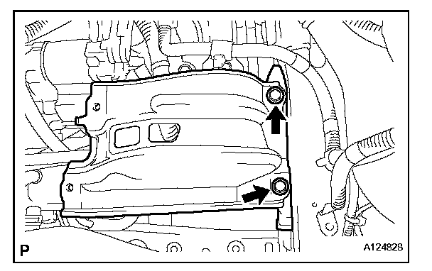
35. INSTALL BATTERY BRACKET REINFORCEMENT
(a) Install the battery bracket reinforcement with the 2 bolts.
Torque: 20 Nm (204 kgf-cm, 15 ft. lbs.)
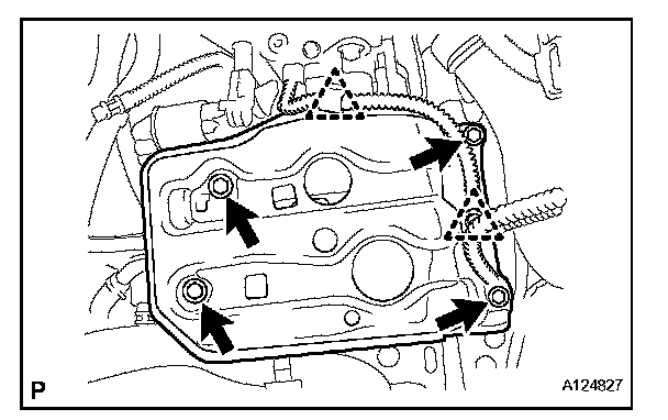
36. INSTALL FRONT BATTERY CARRIER
(a) Install the front battery carrier with the 4 bolts.
Torque: 20 Nm (204 kgf-cm, 15 ft. lbs.)
(b) Connect the 2 clamps of the engine wire.
37. INSTALL AIR CLEANER CASE SUB-ASSEMBLY
(a) Connect the air cleaner case to the No. 1 air cleaner inlet.
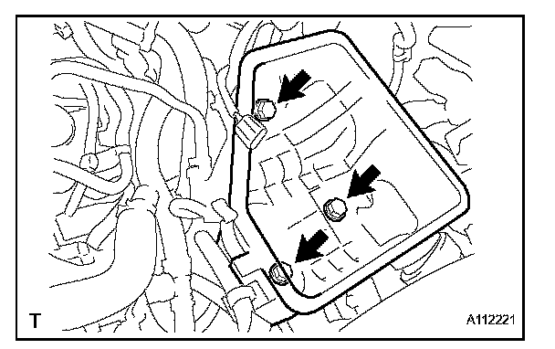
(b) Install the air cleaner case with the 3 bolts.
Torque: 5.0 Nm (51 kgf-cm, 44 inch lbs.)
38. INSTALL AIR CLEANER FILTER ELEMENT SUB-ASSEMBLY
39. INSTALL AIR CLEANER CAP
40. INSTALL PURGE VSV
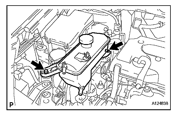
41. INSTALL RADIATOR RESERVOIR
(a) Install the reservoir with the 2 bolts.
Torque: 5.0 Nm (51 kgf-cm, 44 inch lbs.)
42. INSTALL RADIATOR ASSEMBLY
(a) Install the radiator.
43. INSTALL BATTERY TRAY
44. INSTALL BATTERY
(a) Install the battery.
(b) Install the battery clamp with the bolt and nut.
Torque:
8.5 Nm (87 kgf-cm, 75 inch lbs.) for bolt
5.0 Nm (51 kgf-cm, 44 inch lbs.) for nut
45. CONNECT CABLE TO NEGATIVE BATTERY TERMINAL
46. ADD AUTOMATIC TRANSAXLE FLUID
(a) Add automatic transaxle fluid for U241E (2WD).
(b) Add automatic transaxle fluid for U140F (4WD).
47. INSPECT FOR FUEL LEAK
48. ADD ENGINE COOLANT
49. INSPECT FOR ENGINE COOLANT LEAK
(a) Check for engine coolant leaks.
50. INSPECT FOR AUTOMATIC TRANSAXLE FLUID LEAK
51. ADJUST SHIFT LEVER POSITION
(a) Adjust the shift lever position for U241E (2WD).
(b) Adjust the shift lever position for U140F (4WD).
52. INSTALL NO. 1 ENGINE COVER
53. INSTALL FRONT FENDER APRON RH
54. INSTALL NO. 2 ENGINE UNDER COVER
55. INSTALL NO. 1 ENGINE UNDER COVER
56. INSTALL FRONT WHEEL
57. INSTALL RADIATOR SUPPORT OPENING COVER
58. INSTALL HOOD SUB-ASSEMBLY
(a) Install the hood.
(b) Adjust the hood.
59. INSPECT AND ADJUST FRONT WHEEL ALIGNMENT
(a) Inspect and adjust the front wheel alignment.
60. PERFORM REGISTRATION Programming and Relearning
(a) When replacing the engine assembly, perform vehicle stability control system recognition in ECM.
61. RESET MEMORY (for Automatic Transaxle)
(a) When replacing the engine assembly, perform the RESET MEMORY procedure (A/T initialization) for U241E (2WD) and for U140F (4WD). Initialization