Wireless Door Lock Control System
TERMINALS OF ECU1. INSTRUMENT PANEL JUNCTION BLOCK (MULTIPLEX NETWORK BODY ECU)
a. Disconnect the B6, B7 and B9 ECU connectors.
Terminals Of Control Module/Pinouts - Instrument Panel Junction Block (Multiplex Network Body ECU) (Part 1):
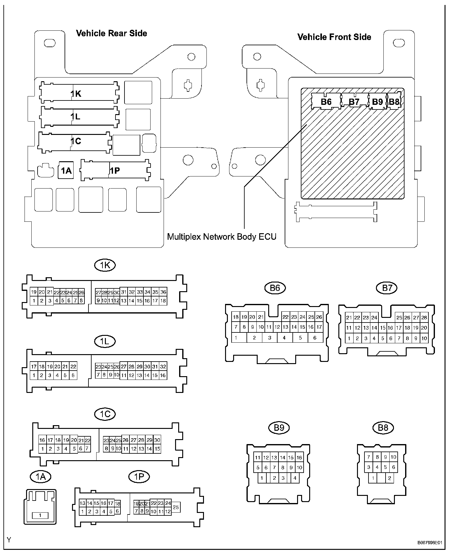
b. Disconnect the 1A, 1C, 1K, 1L and 1P J/B connectors.
Terminals Of Control Module/Pinouts - Instrument Panel Junction Block (Multiplex Network Body ECU) (Part 2):
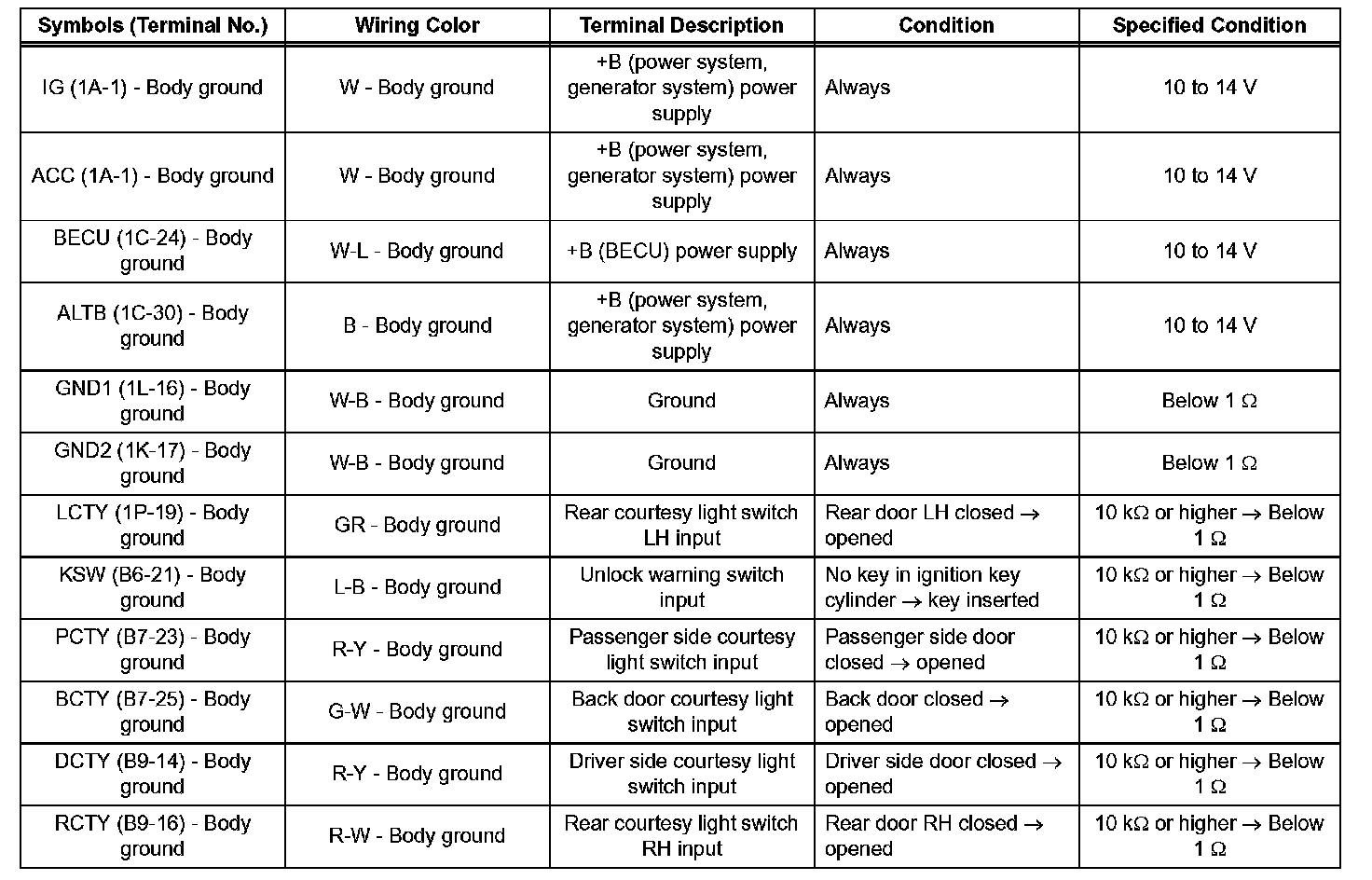
c. Check the voltage or resistance according to the value(s) in the table below (wire harness side connector).
HINT: If the result is not as specified, there may be a malfunction on the wire harness side.
d. Reconnect the B6, B7 and B9 ECU connectors
e. Reconnect the 1A, 1C, 1K, 1L and 1P J/B connectors.
Terminals Of Control Module/Pinouts - Instrument Panel Junction Block (Multiplex Network Body ECU) (Part 3):
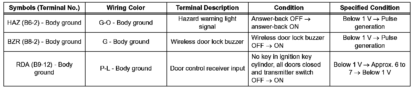
f. Check the voltage according to the value(s) in the table below (ECU side connector).
If the result is not as specified, the instrument panel
J/B (multiplex network body ECU) may have a malfunction.