Air Fuel Ratio Sensor (For 4WD)
REMOVAL1. DISCONNECT CABLE FROM NEGATIVE BATTERY TERMINAL
CAUTION: Wait at least 90 seconds after disconnecting the cable from the negative (-) battery terminal to prevent airbag and seat belt pretensioner activation.
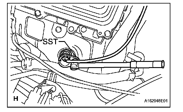
2. REMOVE AIR FUEL RATIO SENSOR (for Bank 2 Sensor 1)
a. Disconnect the sensor connector.
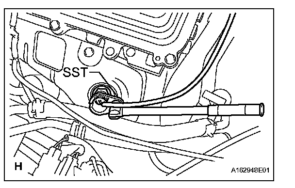
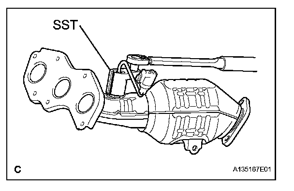
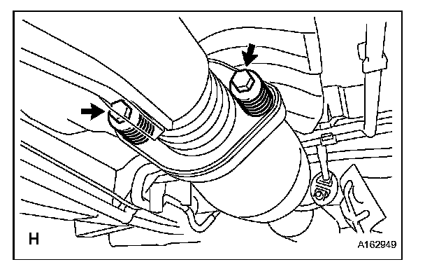
b. Using SST, remove the sensor from the exhaust manifold.
SST 09224-00010
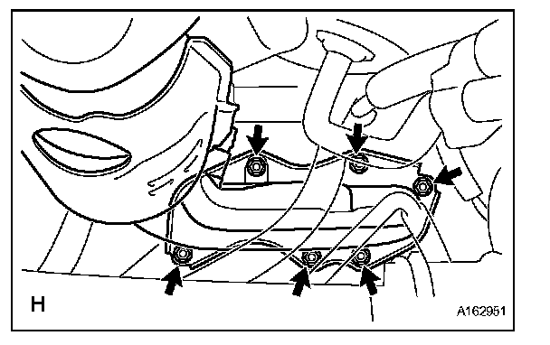
3. REMOVE CENTER EXHAUST PIPE ASSEMBLY
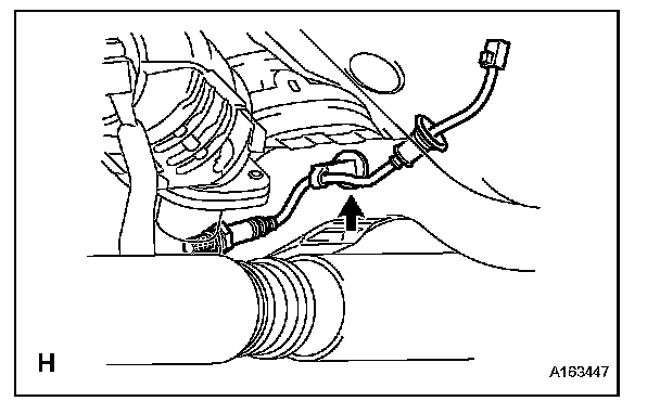
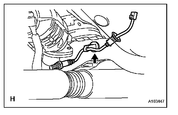
a. Disconnect the heated oxygen sensor (for Bank 1 Sensor 2) connector under the center console.
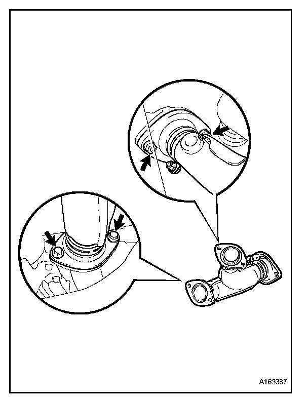
b. Remove the clip as shown in the illustration.
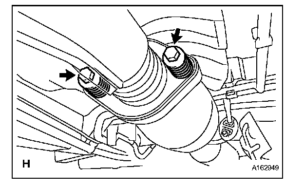
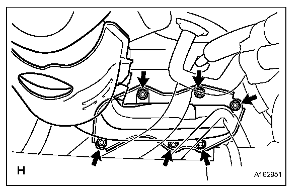
c. Remove the 2 bolts and 2 compression springs.
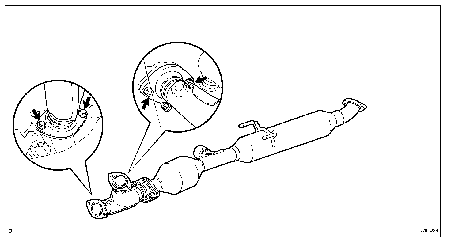
d. Remove the 2 bolts, 2 nuts and center exhaust pipe assembly.
4. REMOVE EXHAUST MANIFOLD RH
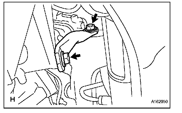
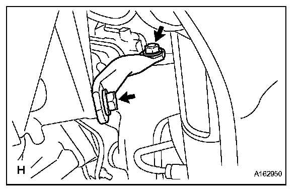
a. Remove the nut, bolt and exhaust manifold stay.
b. Remove the 6 nuts and exhaust manifold RH.
c. Remove the gasket and exhaust manifold to head gasket.
5. REMOVE AIR FUEL RATIO SENSOR (for Bank 1 Sensor 1)
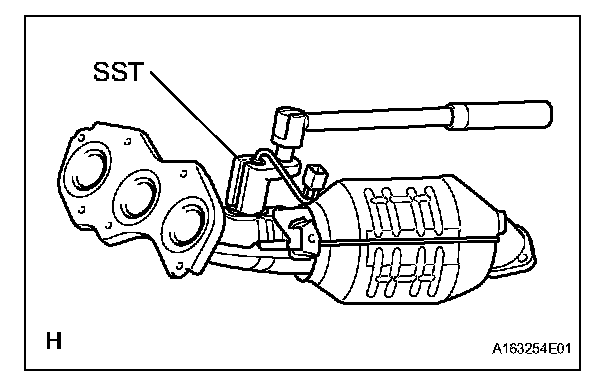
a. Using SST, remove the sensor.
SST 09224-00010
INSTALLATION
1. INSTALL AIR FUEL RATIO SENSOR (for Bank 2 Sensor 1)
a. Using SST, install the sensor to the exhaust manifold LH.
SST 09224-00010
Torque:
40 Nm (408 kgf.cm, 30 ft. lbs.) for use with SST
44 Nm (449 kgf.cm, 32 ft. lbs.) for use without SST
HINT:
- Use a torque wrench with a fulcrum length of 30 cm (11.81 in.).
- Make sure that SST and wrench are connected in a straight line.
b. Connect the sensor connector.
2. INSTALL AIR FUEL RATIO SENSOR (for Bank 1 Sensor 1)
a. Using SST, install the sensor to the exhaust manifold RH.
SST 09224-00010
Torque:
40 Nm (408 kgf.cm, 30 ft. lbs.) for use with SST
44 Nm (449 kgf.cm, 32 ft. lbs.) for use without SST
HINT:
- Use a torque wrench with a fulcrum length of 30cm (11.81 in.).
- Make sure that SST and wrench are connected in a straight line.
3. INSTALL EXHAUST MANIFOLD RH
a. Install the exhaust manifold RH with a new gasket and 6 nuts.
Torque: 21 Nm (214 kgf.cm, 15 ft. lbs.)
b. Install the exhaust manifold stay with the nut and bolt.
Torque: 35 Nm (357 kgf.cm, 26 ft. lbs.)
c. Connect the air fuel ratio sensor (for Bank 1 Sensor 2) connector.
4. INSTALL CENTER EXHAUST PIPE ASSEMBLY
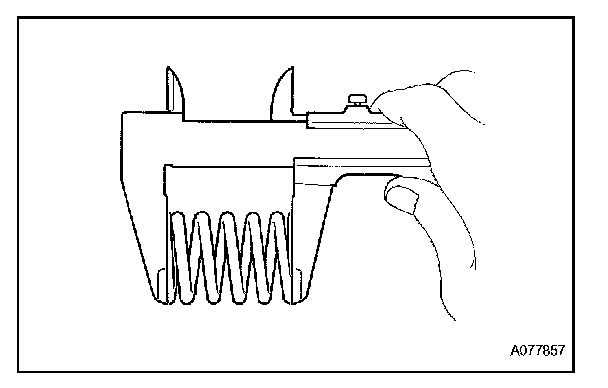
a. Check compression springs.
1. Check the compression springs using vernier calipers.
Specified length: 38.86 mm (1.5299 in.)
HINT: If the result is not as specified, replace the compression spring.
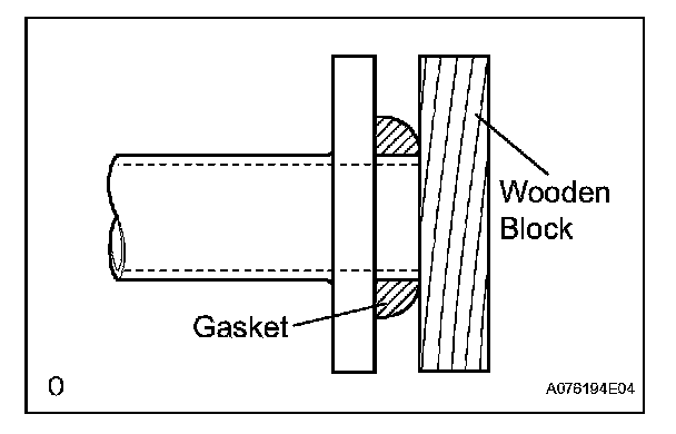
b. Install the gasket.
1. Install a new gasket by hand onto the front exhaust pipe assembly.
2. Using a plastic hammer and wooden block, tap in the new gasket until its surface is flush with the front exhaust pipe.
NOTE:
- Be careful with the installation direction of the gasket.
- Do not damage the gasket.
- Do not reuse the gasket.
- To ensure a proper seal, do not use the exhaust pipe to force the gasket on to the front exhaust pipe.
c. Install 2 new gaskets to the front exhaust pipe assembly.
d. Install the front exhaust pipe assembly with the 2 nuts and 2 bolts.
Torque: Bolt
43 Nm (440 kgf.cm, 32 ft. lbs.)
Nut
62 Nm (632 kgf.cm, 46 ft. lbs.)
e. Install the center exhaust pipe assembly with the 2 compression springs and 2 bolts.
Torque: 43 Nm (438 kgf.cm, 32 ft. lbs.)
f. Attach the clip.
g. Connect the heated oxygen sensor (for Bank 1 Sensor 2) connector.
5. CONNECT CABLE TO NEGATIVE BATTERY TERMINAL
6. INSPECT FOR EXHAUST GAS LEAK