Overhaul
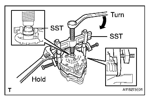
DISASSEMBLY1. REMOVE GENERATOR CLUTCH PULLEY
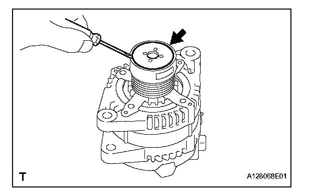
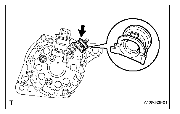
a. Using a screwdriver, remove the generator pulley cap.
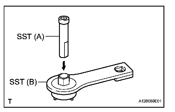
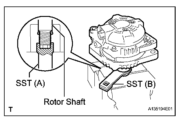
b. Set SST (A) and (B).
SST 09820-63020
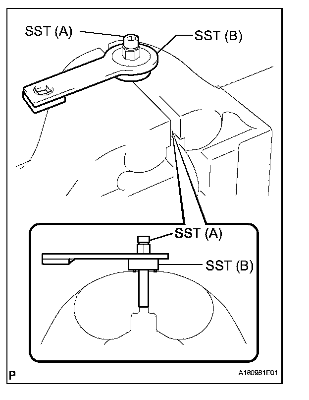
c. Clamp SST (A) in a vise.
NOTE: Be sure to fix the flat surface of SST (A) in a vise.
d. Place the rotor shaft end into SST (A).
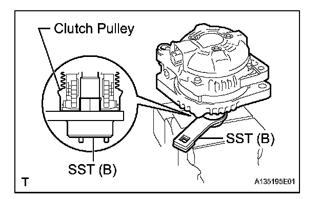
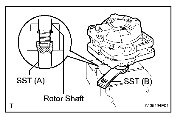
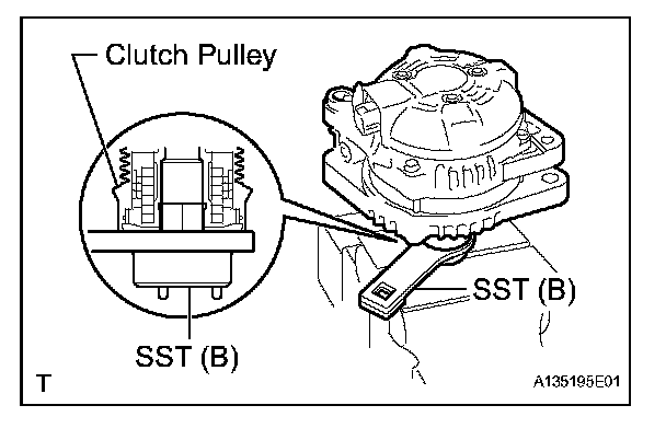
e. Fit SST (B) to the clutch pulley.
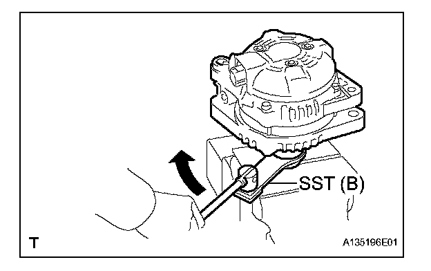
f. Loosen the pulley by turning SST (B) in the direction shown in the illustration.
NOTE: Hold the generator assembly tightly.
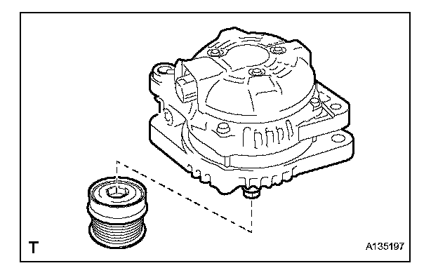
g. Remove the generator assembly from SST
h. Remove the clutch pulley from the rotor shaft.
2. REMOVE GENERATOR REAR END COVER
a. Place the generator assembly on the clutch pulley.
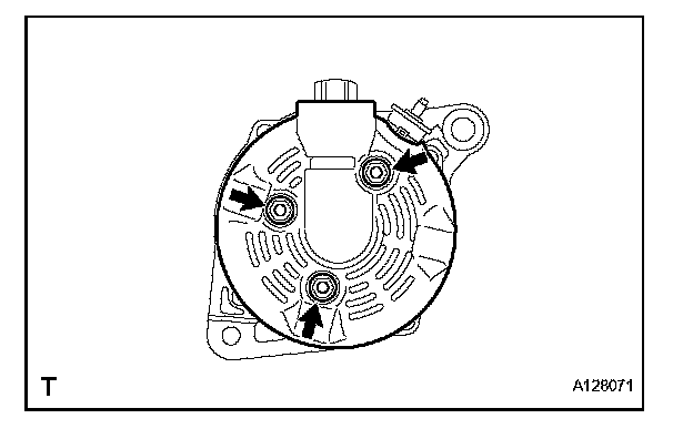
b. Remove the 3 nuts and generator rear end cover.
3. REMOVE GENERATOR TERMINAL INSULATOR
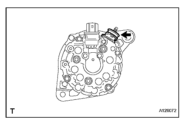
a. Remove the terminal insulator from the generator coil.
4. REMOVE GENERATOR BRUSH HOLDER ASSEMBLY
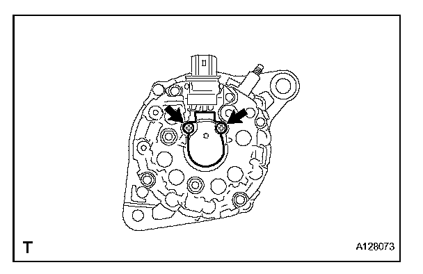
a. Remove the 2 screws and brush holder from the generator coil.
5. REMOVE GENERATOR COIL ASSEMBLY
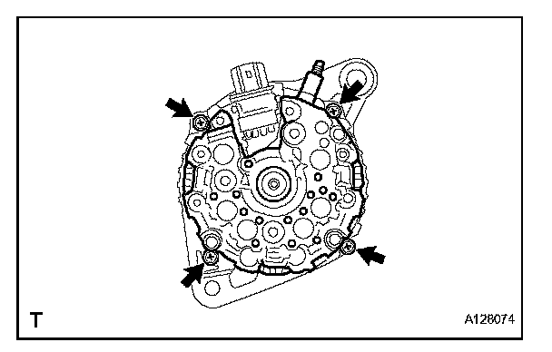
a. Remove the 4 bolts.
b. Using SST, remove the generator coil assembly.
SST 09950-40011(09951-04020, 09952-04010, 09953-04020, 09954-04010, 09955-04071, 09957-04010, 09958-04011)
6. REMOVE GENERATOR ROTOR ASSEMBLY
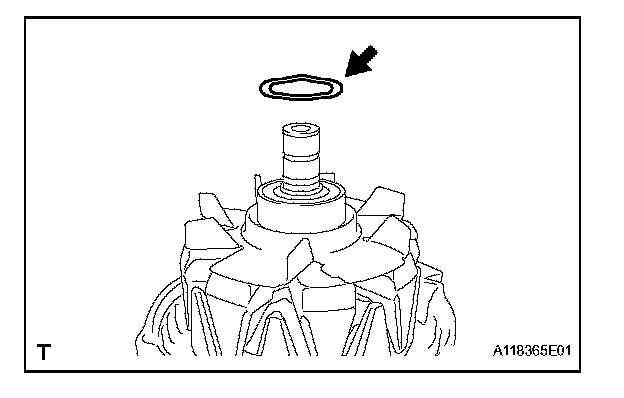
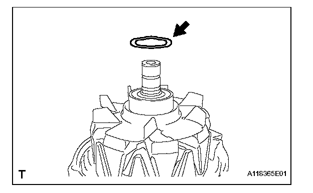
a. Remove the generator washer.
b. Remove the generator rotor assembly.
REASSEMBLY
1. INSTALL GENERATOR ROTOR ASSEMBLY
a. Place the drive end frame on the clutch pulley
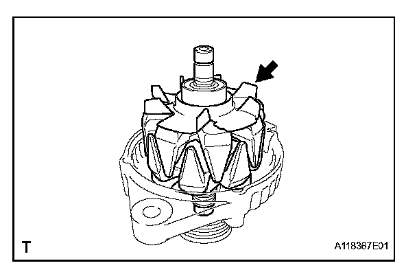
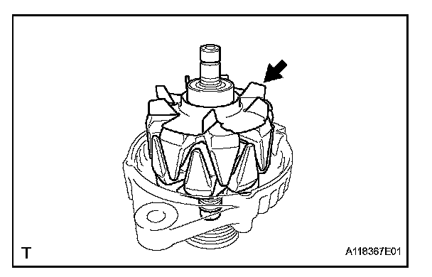
b. Install the generator rotor assembly to the drive end frame.
c. Place a new generator washer on the generator rotor.
2. INSTALL GENERATOR COIL ASSEMBLY
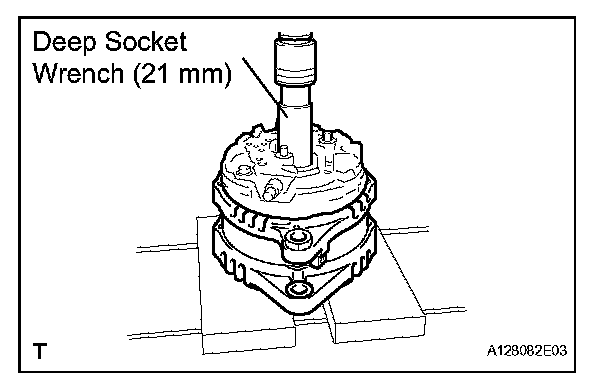
a. Using a deep socket wrench (21 mm) and a press, slowly press in the generator coil assembly.
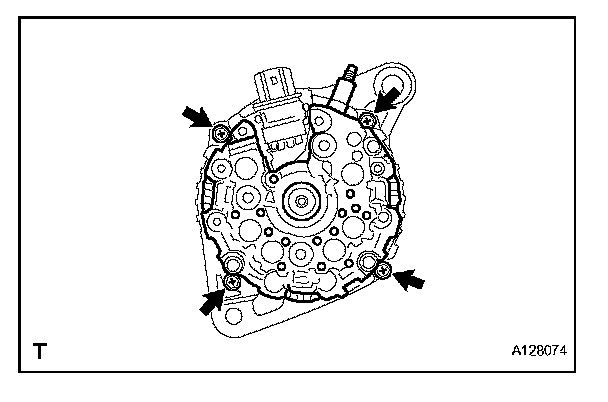
b. Install the 4 bolts.
Torque: 5.8 N.m (59 kgf.cm, 51 in.lbf)
3. INSTALL GENERATOR BRUSH HOLDER ASSEMBLY
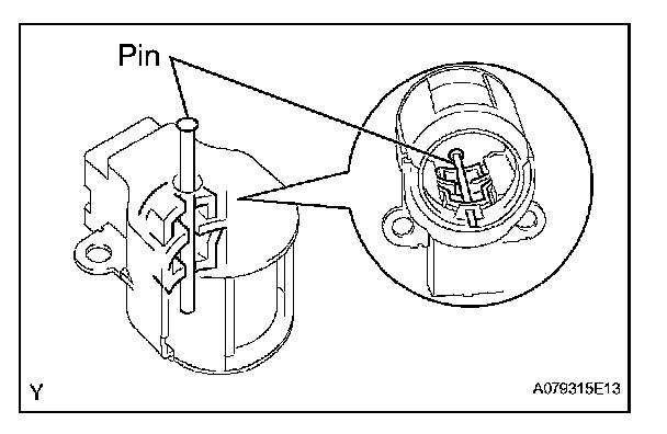
a. While pushing the 2 brushes into the generator brush holder assembly, insert a Dia 1.0 mm (0.039 in.) pin into the brush holder hole.
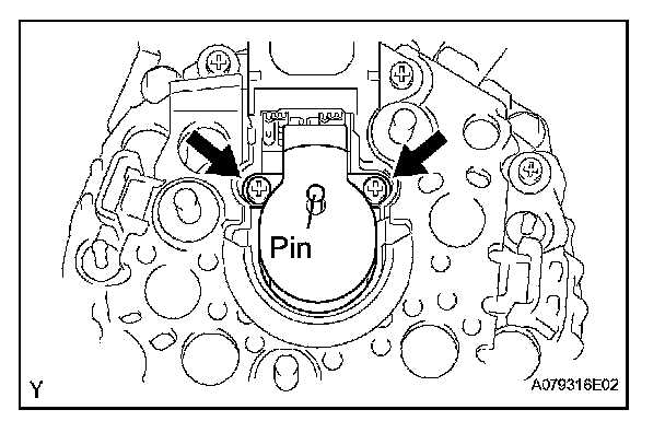
b. Install the brush holder assembly to the generator coil with the 2 screws.
Torque: 1.8 N.m (18 kgf.cm, 16 in.lbf)
c. Pull out the pin from the generator brush holder.
4. INSTALL GENERATOR TERMINAL INSULATOR
a. Install the terminal insulator to the generator coil.
NOTE: Pay attention to installation direction of the terminal insulator.
5. INSTALL GENERATOR REAR END COVER
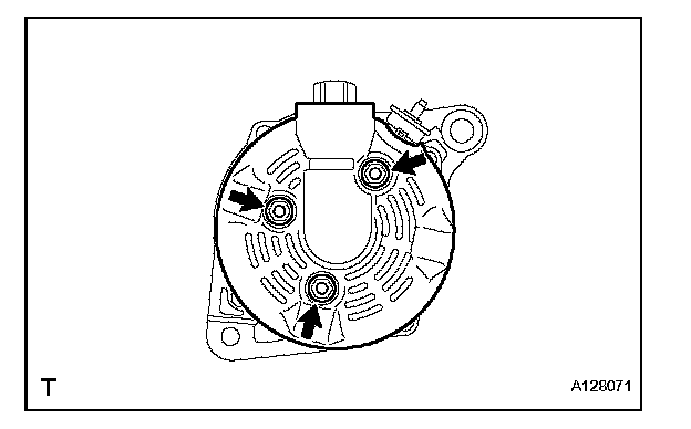
a. Install the generator rear end cover to the generator coil with the 3 nuts.
Torque: 4.6 N.m (47 kgf.cm, 41 in.lbf)
6. INSTALL GENERATOR CLUTCH PULLEY
a. Temporarily install the clutch pulley onto the rotor shaft.
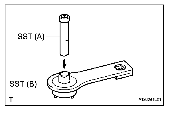
b. Set SST (A) and (B).
SST 09820-63020
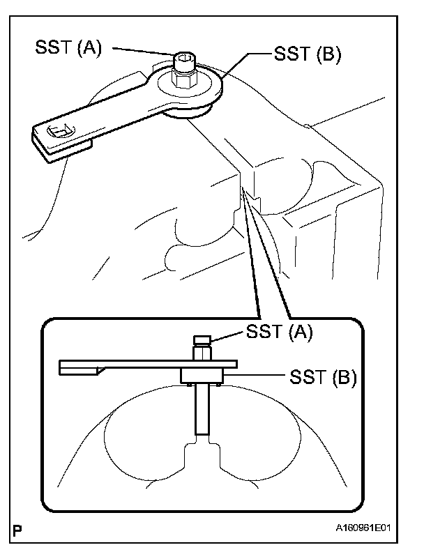
c. Clamp SST (A) in a vise.
NOTE: Be sure to fix the flat surface of SST (A) in a vise.
d. Place the rotor shaft end into SST (A).
e. Fit SST (B) to the clutch pulley.
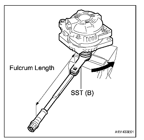
f. Tighten the pulley by turning SST (B) in the direction shown in the illustration.
Torque:
without SST 110 N.m (1125 kgf.cm, 81 ft.lbf)
with SST 84 N.m (857 kgf.cm, 62 ft.lbf)
NOTE:
- Use a torque wrench with a fulcrum length of 31.8 mm (12.52 in.).
- This torque value is effective when SST is parallel to a torque wrench.
- Hold the generator assembly tightly.
g. Remove the generator assembly from SST.
h. Check that the clutch pulley rotates smoothly
i. Install a new clutch pulley cap to the clutch pulley.