Pinout Values and Diagnostic Parameters
TERMINALS OF ECUHINT: This section describes the standard CAN values for all CAN related components.
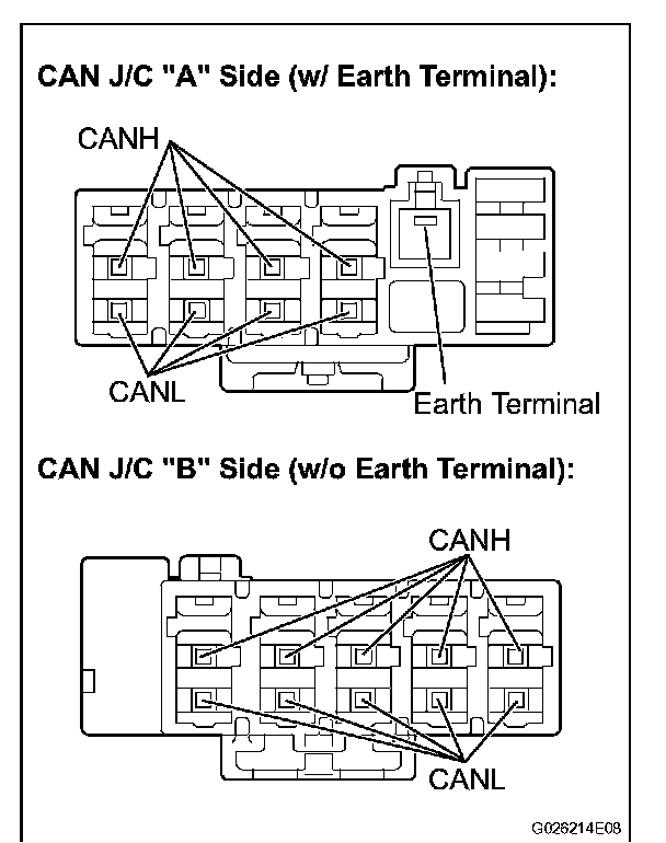
1. CAN JUNCTION CONNECTOR
a. CAN J/C connectors.
HINT:
- The connectors connected to the CAN J/C can be distinguished by the colors of the bus lines and the connecting side of the connector.
- J7, J8, J9 and J10 are interchangeable.
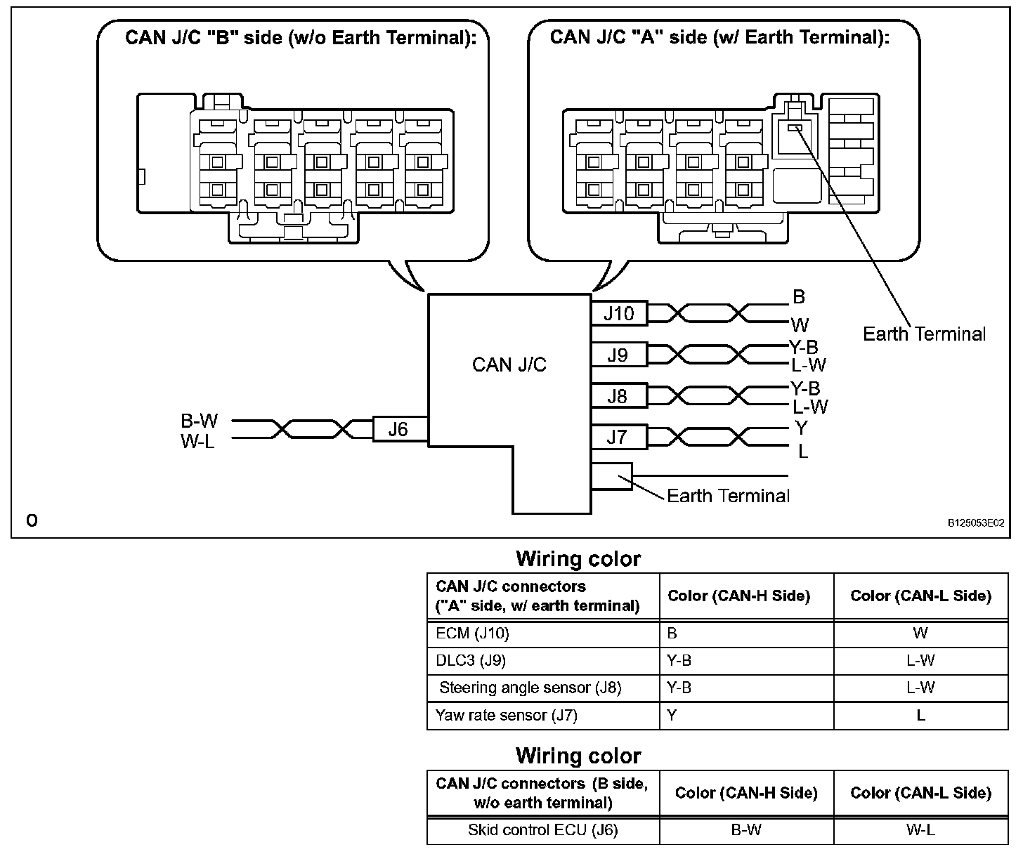
b. The terminals of the CAN J/C connectors.
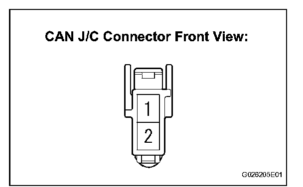
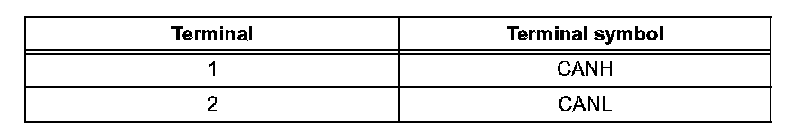
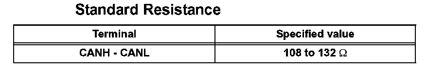
c. Measure the resistance according to the value(s) in the table.
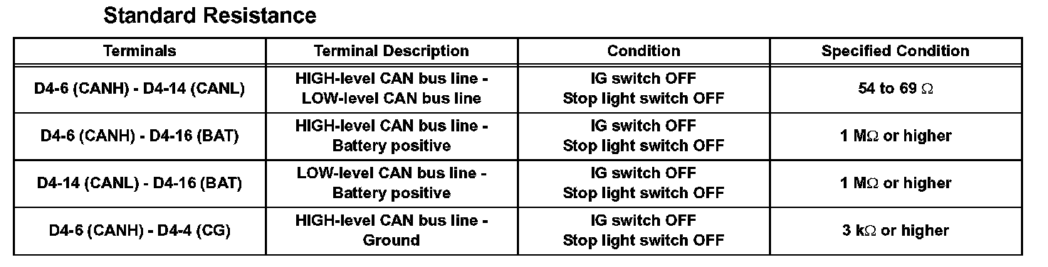
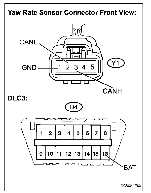
2. DLC3
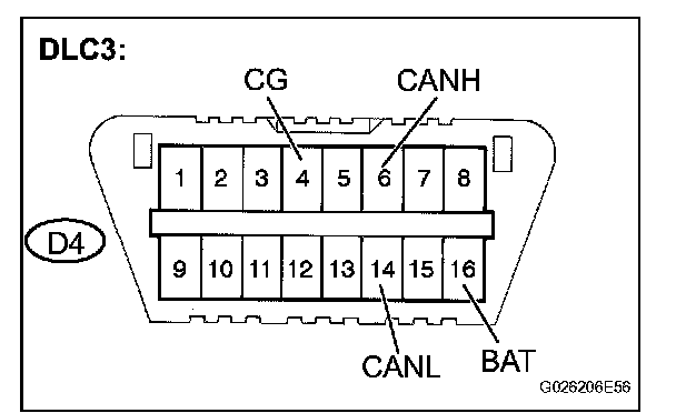
a. Measure the resistance according to the value(s) in the table.

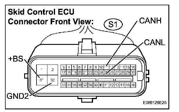
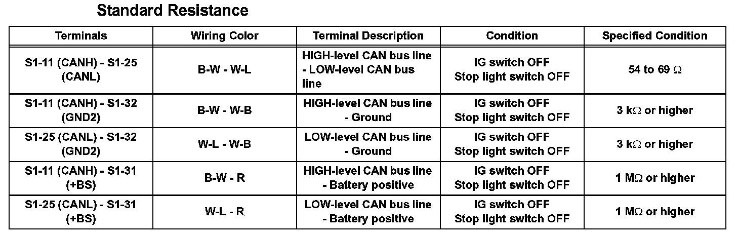
3. SKID CONTROL ECU
a. Check the skid control ECU harness side connector (S1).
1. Disconnect the connector (S1) from the skid control ECU.
2. Measure the resistance according to the value(s) in the table.
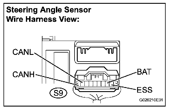
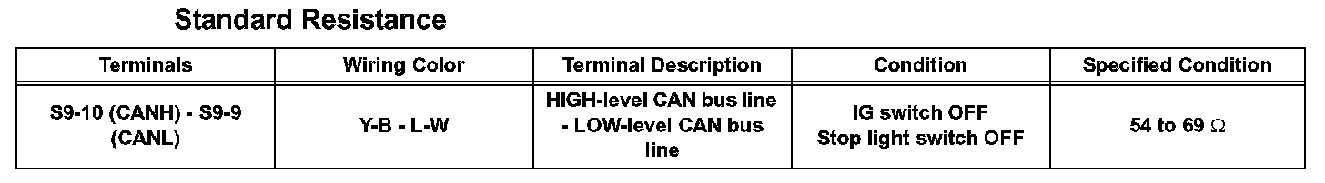
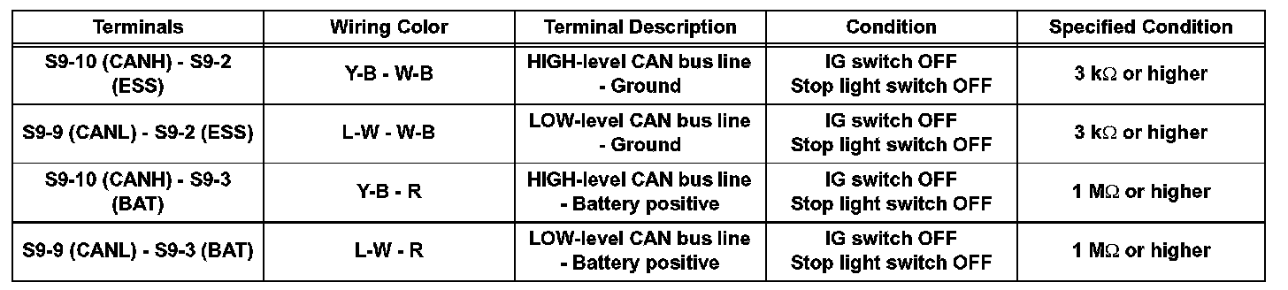
4. STEERING ANGLE SENSOR
a. Check the harness side connector (S9) of the steering angle sensor.
1. Disconnect the connector (S9) from the steering angle sensor.
2. Measure the resistance according to the value(s) in the table.
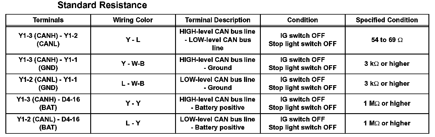
5. YAW RATE SENSOR
a. Check the yaw rate sensor harness side connector (Y1).
1. Disconnect the connector (Y1) from the yaw rate sensor.
2. Measure the resistance according to the value(s) in the table.
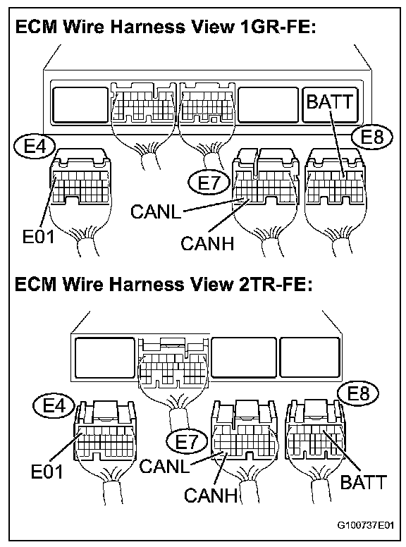
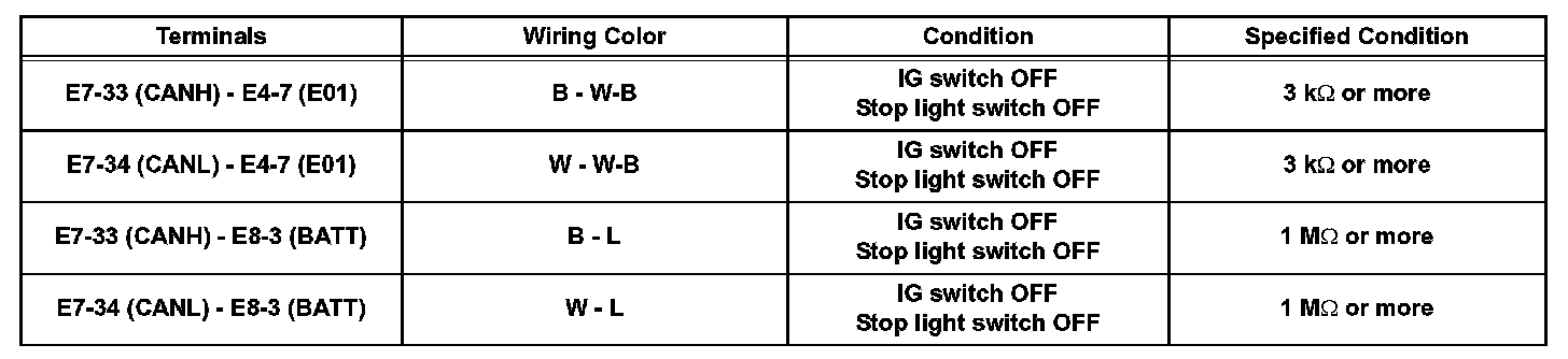
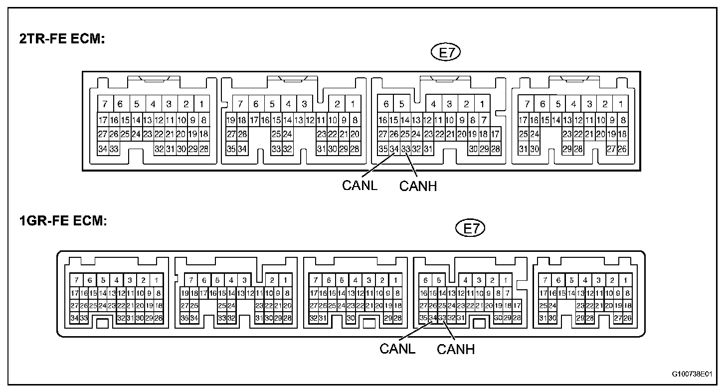
6. ECM
a. Measure the resistance according to the value(s) in the table.
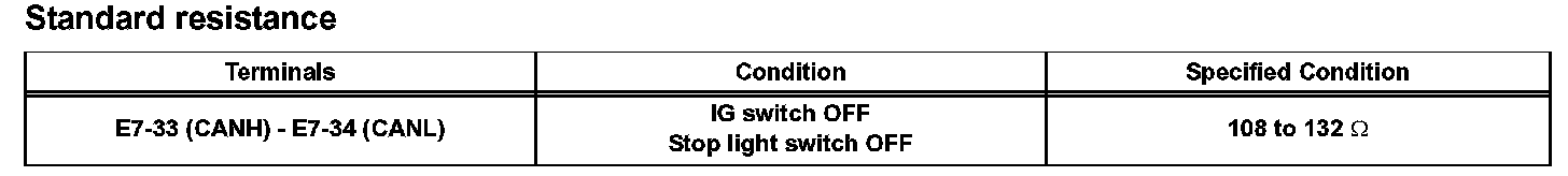
b. Measure the resistance according to the value(s) in the table.