Overhaul
DISASSEMBLY1. REMOVE GENERATOR PULLEY
SST 09820-63011 (09820-06010, 09820-06020)
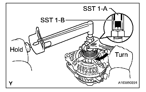

a. Hold SST 1-A with a torque wrench, and tighten SST 1-B clockwise to the specified torque.
Torque: 39 N.m (398 kgf.cm, 29 ft.lbf)
NOTE: Check that SST is secured on the rotor shaft.
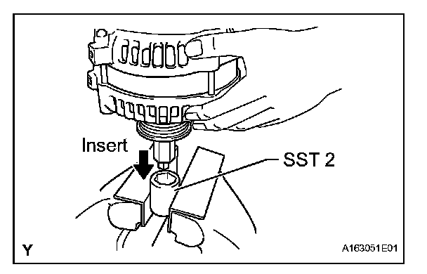
b. Mount SST 2 in a vise.
c. Insert SST 1-A and B into SST 2, and attach the pulley nut to SST 2.
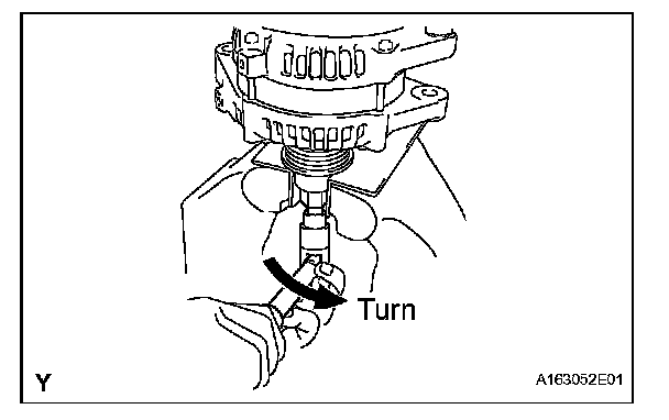
d. To loosen the pulley nut, turn SST 1-A in the direction shown in the illustration.
NOTE: To prevent damage to the rotor shaft, do not loosen the pulley nut more than one-half turn.
e. Remove the generator from SST 2.
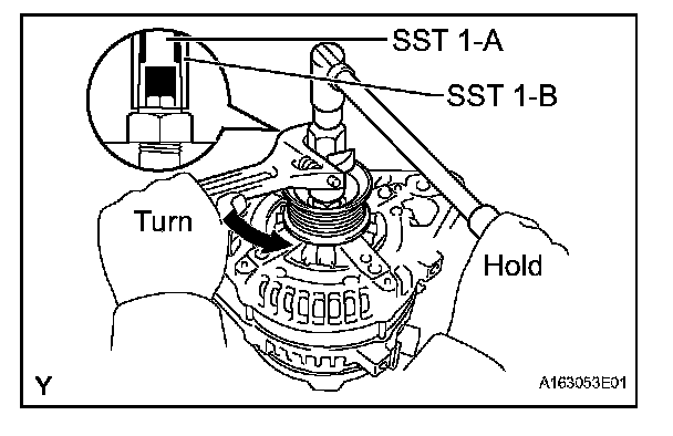
f. Turn SST 1-B, and remove SST 1-A and B.
g. Remove the pulley nut and pulley.
2. REMOVE GENERATOR REAR END COVER
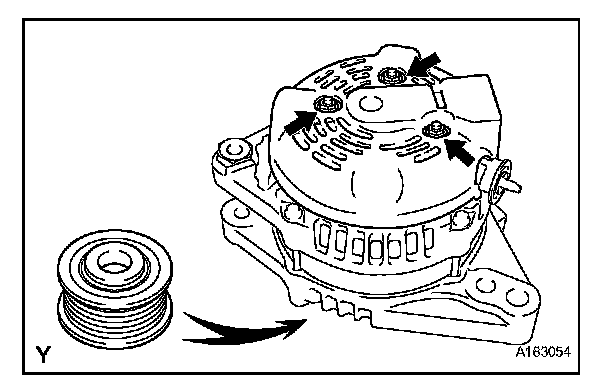
a. Place the generator on the pulley.
b. Remove the 3 nuts, then remove the rear end cover.
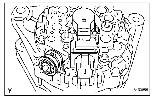
3. REMOVE TERMINAL INSULATOR
4. REMOVE GENERATOR BRUSH HOLDER ASSEMBLY
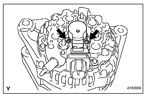
a. Remove the 2 nuts, then remove the brush holder.
5. REMOVE GENERATOR COIL ASSEMBLY
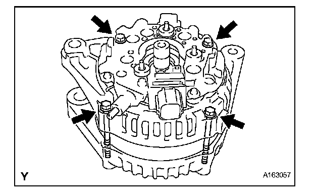
a. Remove the 4 bolts.
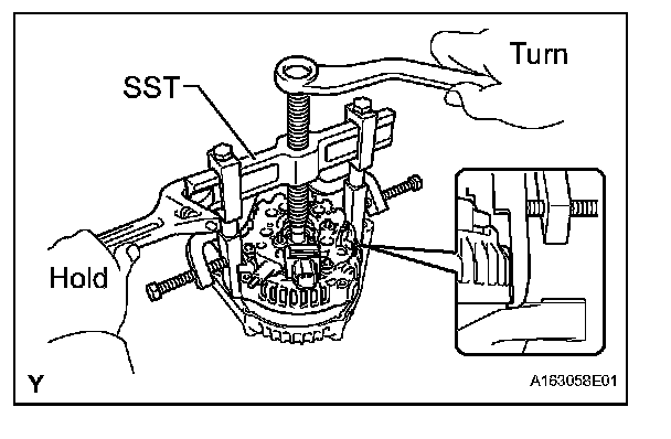
b. Using SST, remove the coil.
SST 09950-40011 (09951-04020, 09952-04010, 09953-04020, 09954-04010, 09955-04071, 09957-04010, 09958-04011)
6. REMOVE GENERATOR ROTOR ASSEMBLY
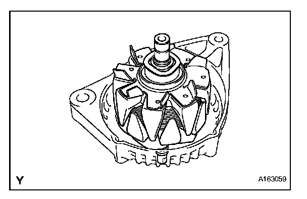
a. Remove the generator washer and the generator rotor.
7. REMOVE GENERATOR DRIVE END FRAME BEARING
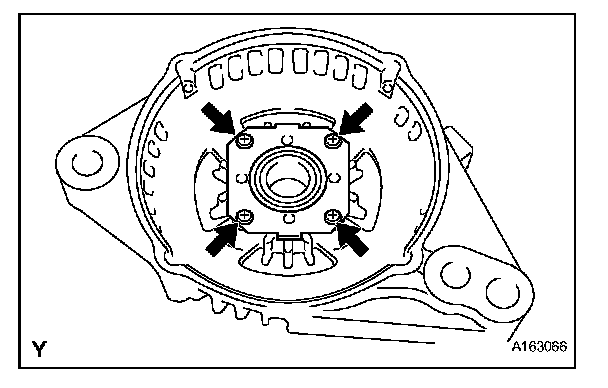
a. Remove the 4 screws and retainer plate.
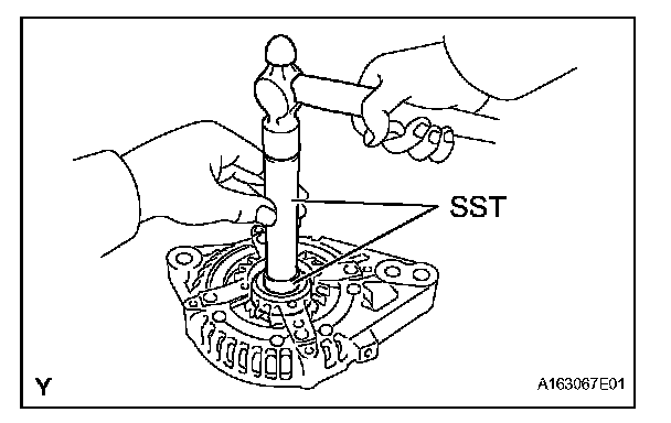
b. Using SST and a hammer, tap out the bearing.
SST 09950-60010 (09951-00250), 09950-70010 (09951-07100)
REASSEMBLY
1. INSTALL GENERATOR DRIVE END FRAME BEARING
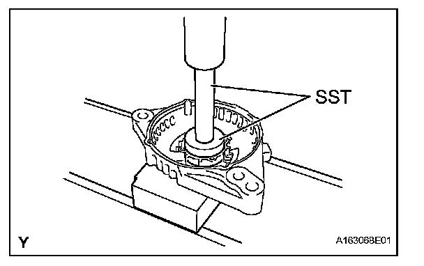
a. Using SST and a press, press in a new bearing.
SST 09950-60010 (09951-00470), 09950-70010(09951-07100)
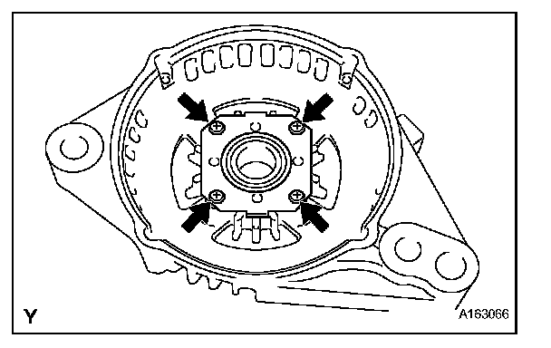
b. Install the retainer plate with the 4 screws.
Torque: 2.3 N.m (23 kgf.cm, 20 in.lbf)
2. INSTALL GENERATOR ROTOR ASSEMBLY
a. Place the drive end frame on the rotor.
b. Install the rotor and washer.
3. INSTALL GENERATOR COIL ASSEMBLY
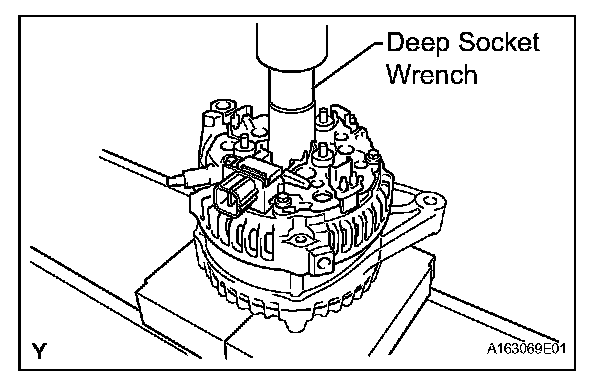
a. Using a 21 mm deep socket wrench and a press, push in the generator rectifier end frame carefully.
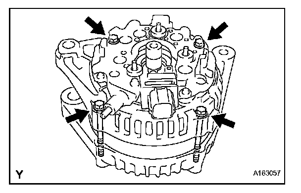
b. Install the 4 bolts.
Torque: 5.8 N.m (59 kgf.cm, 51 in.lbf)
4. INSTALL GENERATOR BRUSH HOLDER ASSEMBLY
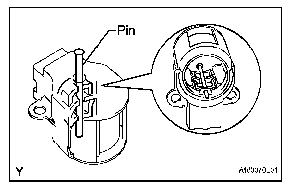
a. While pushing the 2 brushes toward the inside of the brush holder, insert a pin (diameter: 1.0 mm (0.0394 in.)) into the brush holder hole.
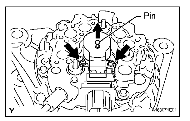
b. Install the generator brush holder with the 2 screws.
Torque: 1.8 N.m (18 kgf.cm, 16 in.lbf)
c. Pull out the pin from the generator brush holder.
5. INSTALL TERMINAL INSULATOR
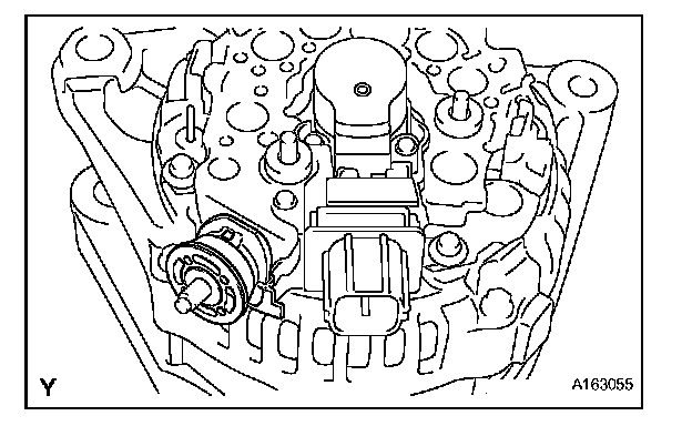
a. Install the terminal insulator to the generator rectifier end frame.
NOTE: Pay attention to the mounting orientation of the terminal insulator.
6. INSTALL GENERATOR REAR END COVER
a. Install the rear end cover with the 3 nuts.
Torque: 4.6 N.m (47 kgf.cm, 41 in.lbf)
7. INSTALL GENERATOR PULLEY
SST 09820-63011 (09820-06010, 09820-06020)
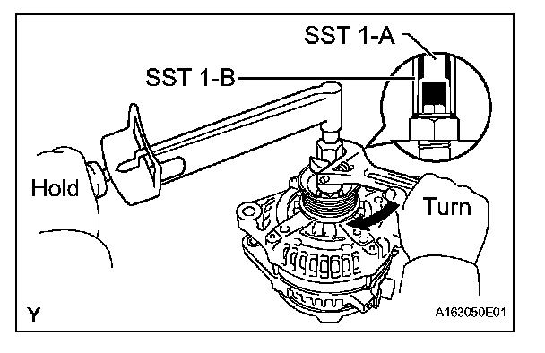

a. Install the pulley onto the rotor shaft by tightening the pulley nut by hand.
b. Hold SST 1-A with a torque wrench, and tighten SST 1-B clockwise to the specified torque.
Torque: 39 N.m (398 kgf.cm, 29 ft.lbf)
NOTE: Check that SST is secured to the rotor shaft.
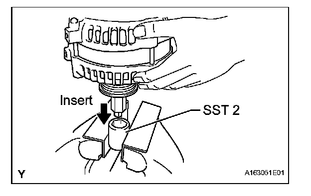
c. Mount SST 2 in a vise.
d. Insert SST 1-A and B into SST 2, and attach the pulley nut to SST 2.
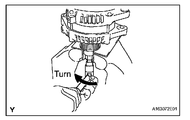
e. Tighten the pulley nut by turning SST 1-A in the direction shown in the illustration.
Torque: 133 N.m (1356 kgf.cm, 98 ft.lbf)
f. Remove the generator from SST 2.
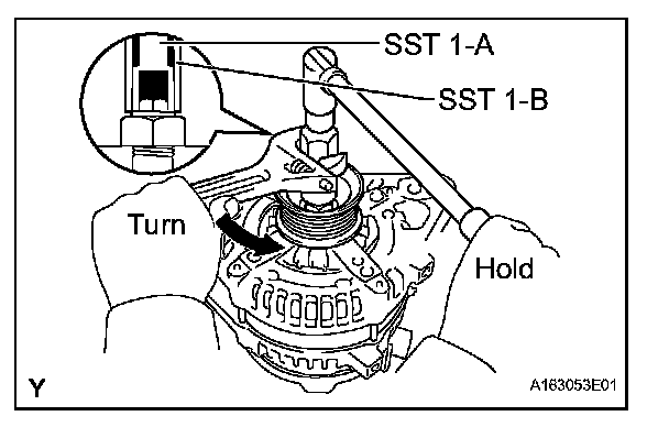
g. Turn SST 1-B, and remove SST 1-A and B.
h. Turn the pulley and check that the pulley moves smoothly.