Air Injection Control Valve: Service and Repair
REMOVAL1. REMOVE EXHAUST MANIFOLD SUB-ASSEMBLY
a. Remove the exhaust manifold.
2. REMOVE INTAKE MANIFOLD
a. Remove the intake manifold.
3. DISCONNECT NO. 1 WATER BY-PASS HOSE
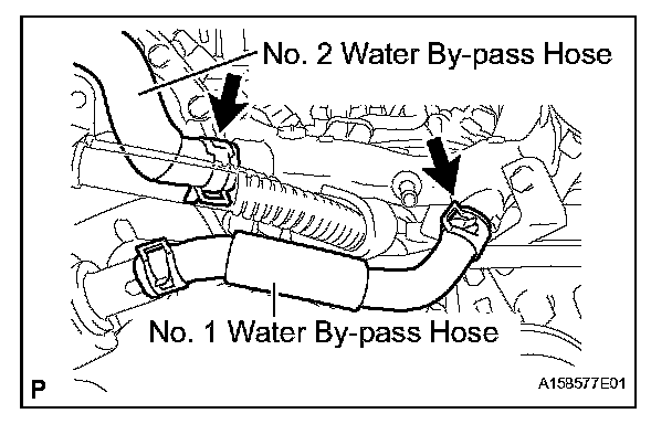
a. Disconnect the No. 1 water by-pass hose from the water by-pass joint and water inlet housing.
4. DISCONNECT NO. 2 WATER BY-PASS HOSE
a. Disconnect the No. 2 water by-pass hose from the water by-pass joint.
5. DISCONNECT NO. 2 WATER BY-PASS PIPE SUBASSEMBLY
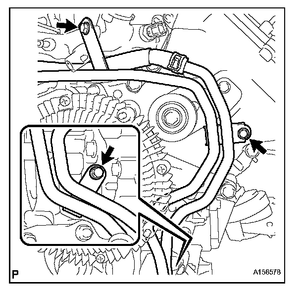
a. Remove the 3 bolts and disconnect the No. 2 water by-pass pipe.
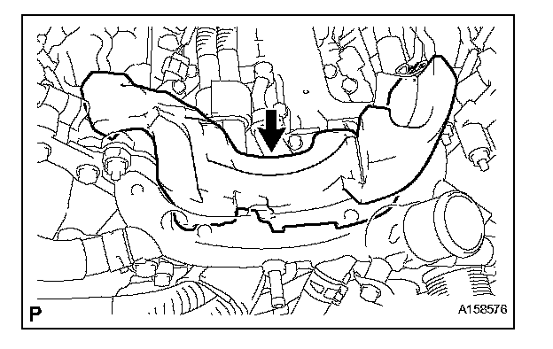
6. REMOVE NO. 2 ENGINE COVER
7. DISCONNECT FUEL TUBE CLAMP
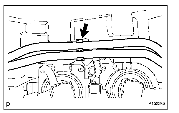
a. Disconnect the fuel tube clamp from the bracket.
8. REMOVE NO. 1 ENGINE COVER
9. REMOVE FRONT WATER BY-PASS JOINT
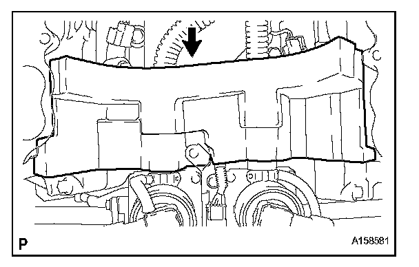
a. Disconnect the engine coolant temperature sensor connector.
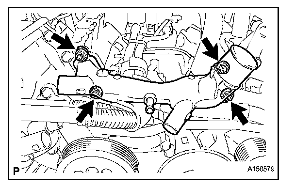
b. Remove the 4 nuts, front water by-pass joint and 2 gaskets.
10. REMOVE AIR TUBE
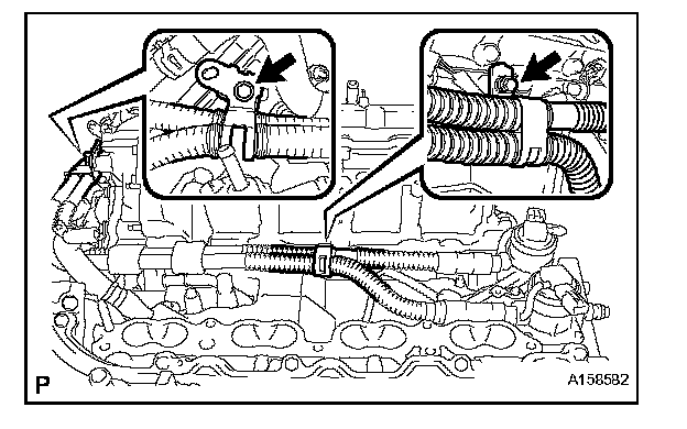
a. Disconnect the No. 2 and No. 3 hoses.
b. Disconnect the air pump's connector.
c. Disconnect the air pump connector clamp's holder.
d. Using a clip remover, detach the wire harness claw.
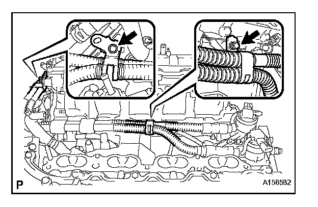
e. Remove the 2 bolts and air tube.
f. Disconnect the 2 No. 1 air hoses from the air tube.
11. REMOVE AIR SWITCHING VALVE ASSEMBLY
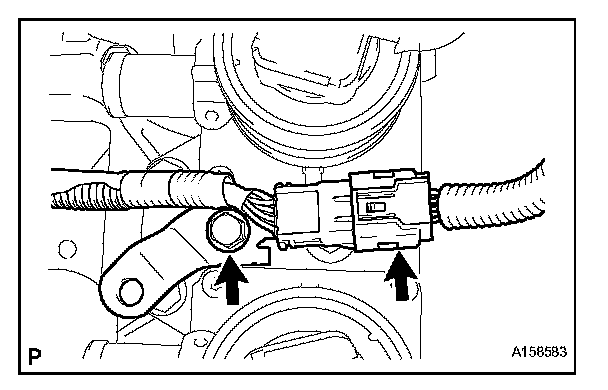
a. Disconnect the knock sensor's connector.
b. Remove the bolt and bracket.
c. Disconnect the 2 air switching valve connectors.
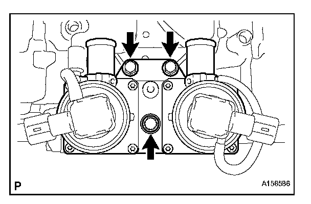
d. Remove the 3 bolts and air switching valve.
12. REMOVE NO. 2 AIR TUBE
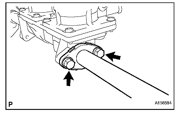
a. Remove the 2 bolts, No. 2 air tube and gasket.
NOTE: Be careful not to damage the installation surface of the gaskets.
13. REMOVE NO. 3 AIR TUBE
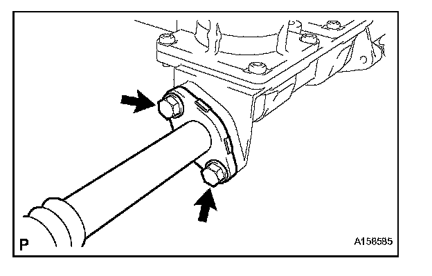
a. Remove the 2 bolts, No. 3 air tube and gasket.
NOTE: Be careful not to damage the installation surface of the gaskets.
INSTALLATION
1. INSTALL NO. 3 AIR TUBE
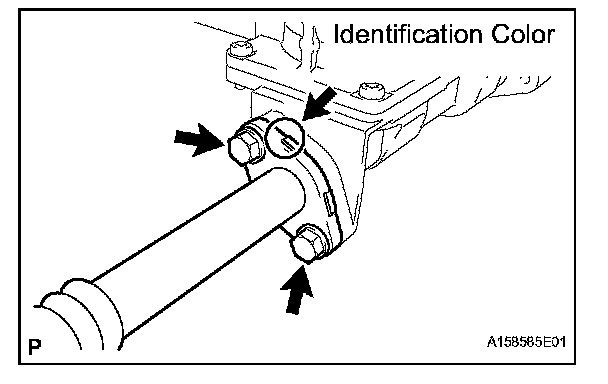
a. Install a new gasket and the No. 3 air tube with the 2 bolts.
Torque: 10 N.m (102 kgf. cm, 7 ft.lbf)
NOTE: Make sure the gasket's claws are not caught between the air tube and air switching valve.
HINT: The identification color on the flange is orange.
2. INSTALL NO. 2 AIR TUBE
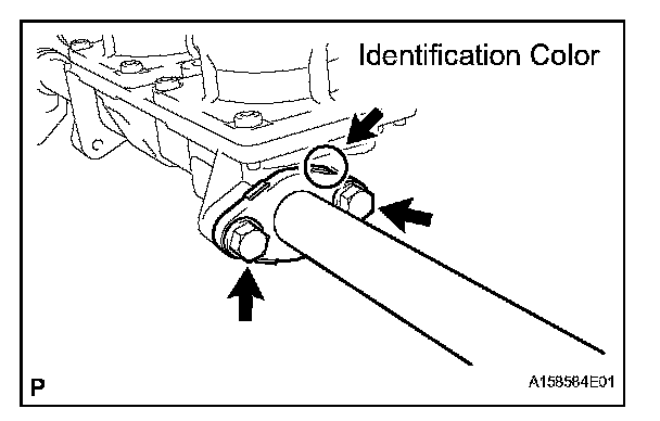
a. Install a new gasket and the No. 2 air tube with the 2 bolts.
Torque: 10 N.m (102 kgf. cm, 7 ft.lbf)
NOTE: Make sure the gasket's claws are not caught between the air tube and air switching valve.
HINT: The identification color on the flange is blue.
3. INSTALL AIR SWITCHING VALVE ASSEMBLY
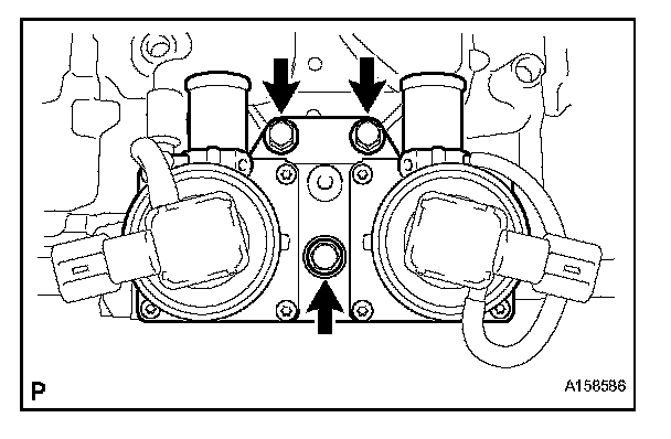
a. Install the air switching valve with the 3 bolts.
Torque: 21 N.m (214 kgf. cm, 15 ft.lbf)
b. Connect the 2 air switching valve connectors.
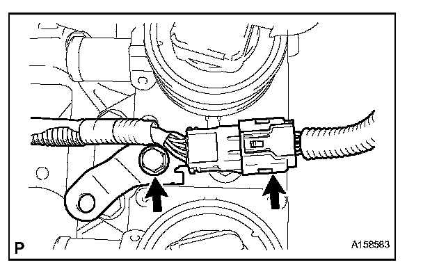
c. Install the bracket with the bolt.
Torque: 8.0 N.m (82 kgf. cm, 71 in.lbf)
d. Connect the knock sensor's connector.
4. INSTALL AIR TUBE
a. Connect the 2 No. 1 air hoses to the air tube.
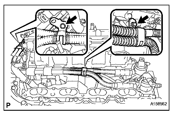
b. Connect the air tube to the air switching valve, and install the air tube with the 2 bolts.
Torque: 10 N.m (102 kgf. cm, 7 ft.lbf)
c. Connect the air pump connector clamp's holder.
d. Attach the wire harness claw.
e. Connect the air pump's connector.
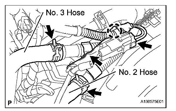
f. Connect the No. 2 and No. 3 hose.
5. INSTALL FRONT WATER BY-PASS JOINT
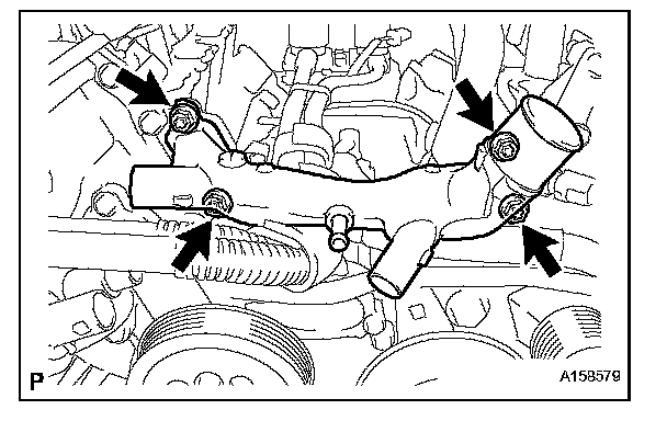
a. Install 2 new gaskets and the front water by-pass joint with the 4 nuts.
Torque: 21 N.m (214 kgf. cm, 15 ft.lbf)
b. Connect the engine coolant temperature sensor connector.
6. CONNECT NO. 2 WATER BY-PASS PIPE SUBASSEMBLY
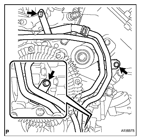
a. Connect the No. 2 water by-pass pipe with the 3 bolts.
Torque: 10 N.m (102 kgf. cm, 7 ft.lbf)
7. CONNECT NO. 2 WATER BY-PASS HOSE
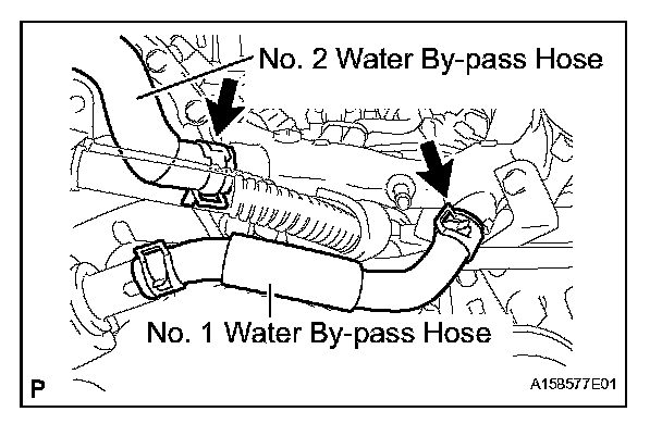
a. Connect the No. 2 water by-pass hose to the water by-pass joint.
8. CONNECT NO. 1 WATER BY-PASS HOSE
a. Connect the No. 1 water by-pass hose to the water by-pass joint and water inlet housing.
9. INSTALL NO. 1 ENGINE COVER
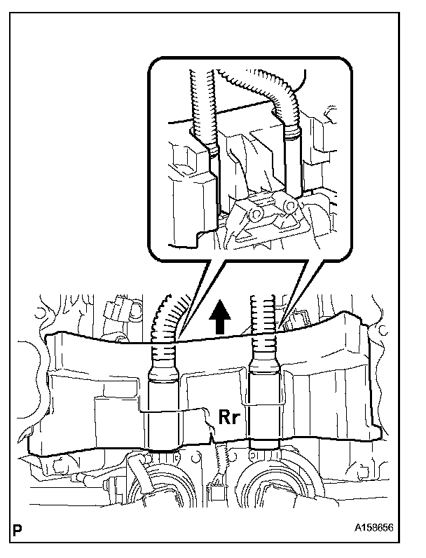
NOTE: Make sure that the No. 1 engine cover is level with the top surface of the intake port of the cylinder head for 1 and 2.
HINT:
- Align the No. 1 engine cover cutouts with the air tube.
- Align the No. 1 engine cover with the air switching valve surface and cylinder head wall.
10. CONNECT FUEL TUBE CLAMP
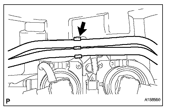
a. Connect the fuel tube clamp to the bracket.
11. INSTALL NO. 2 ENGINE COVER
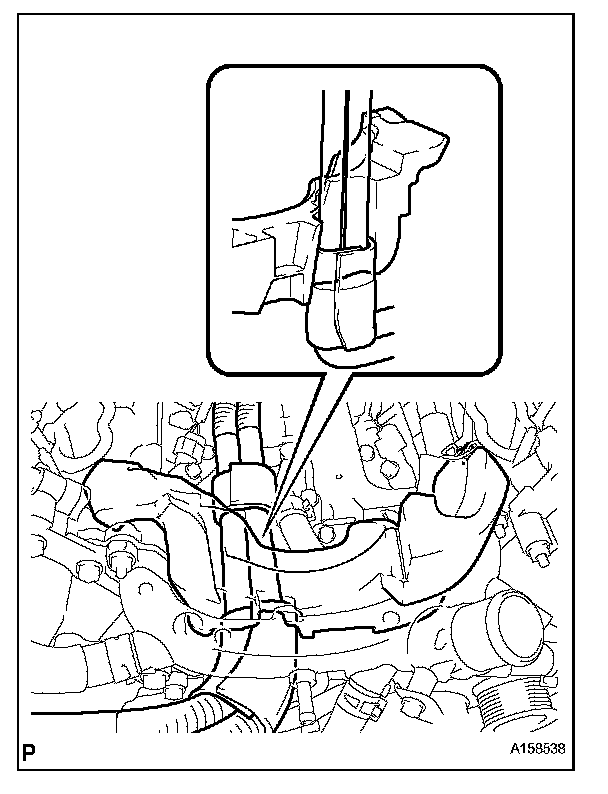
NOTE: Make sure that the No. 2 engine cover is level with the top surface of the intake port if the cylinder head.
HINT:
- Align the No. 2 engine cover cutout with the air tube.
- Align the No. 2 engine cover with the front water bypass joint and cylinder head wall.
12. INSTALL INTAKE MANIFOLD
a. Install the intake manifold.
13. INSTALL EXHAUST MANIFOLD SUB-ASSEMBLY
a. Install the exhaust manifold.