Part 1
ENGINE UNITCOMPONENTS (Part 1):
COMPONENTS (Part 2):
COMPONENTS (Part 3):
COMPONENTS (Part 4):
COMPONENTS (Part 5):
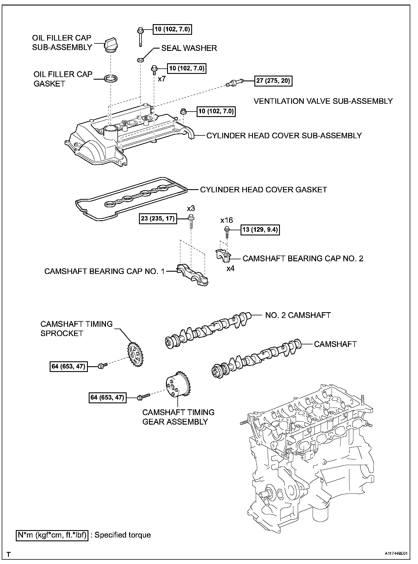
COMPONENTS (Part 6):
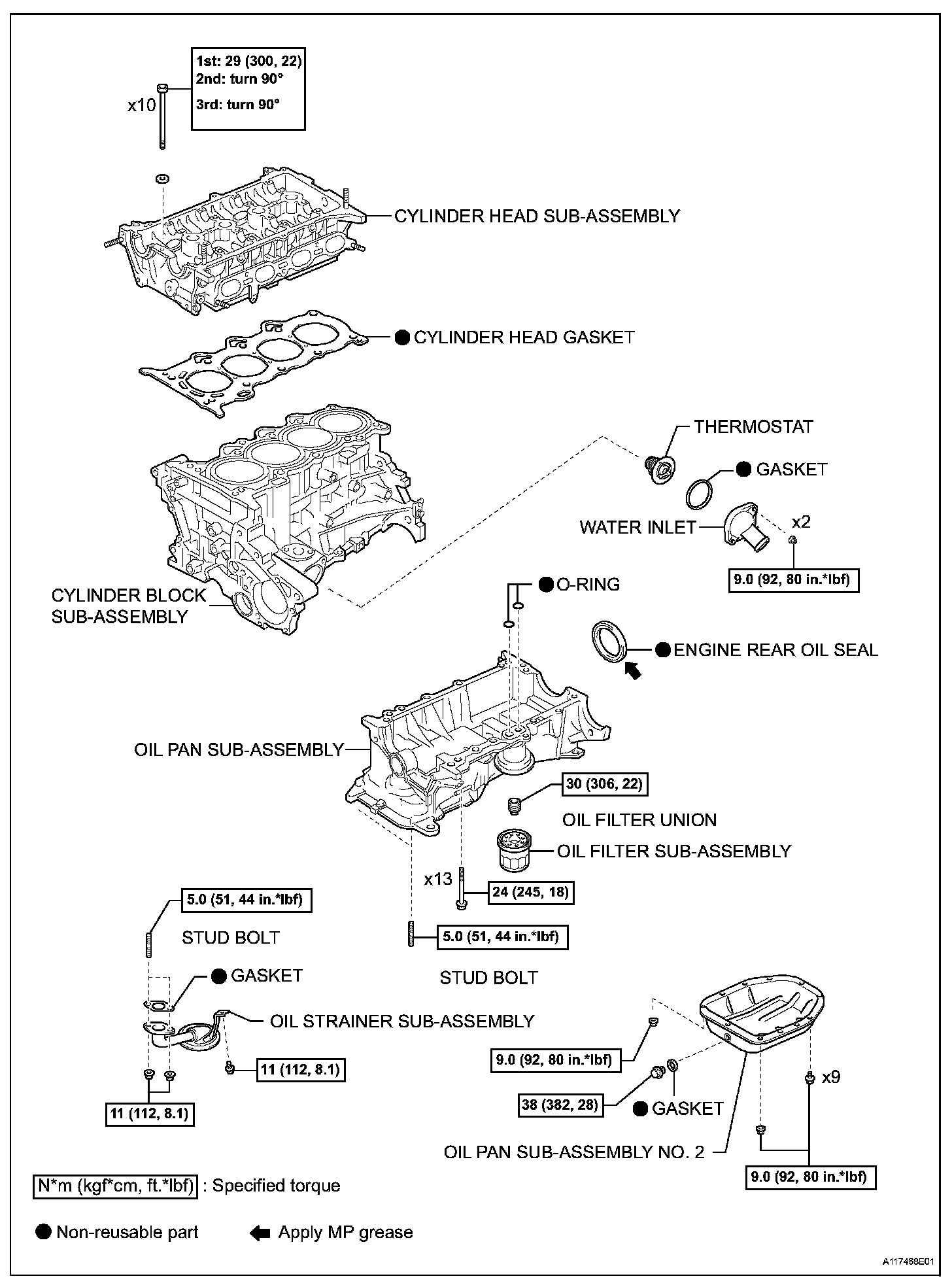
COMPONENTS (Part 7):

COMPONENTS (Part 8):
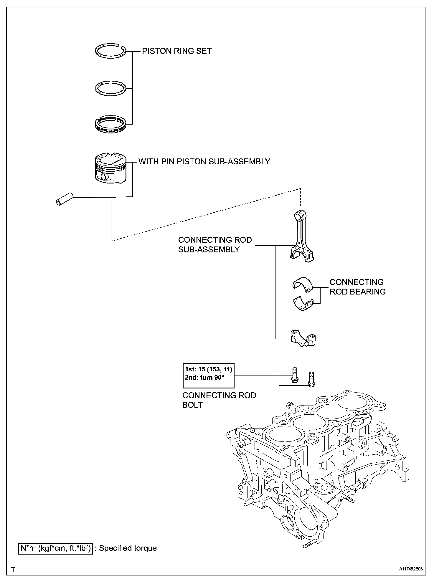
INSPECTION
1. INSPECT CAMSHAFT TIMING GEAR ASSEMBLY
(a) Check the lock of camshaft timing gear.
(1) Clamp the camshaft in a vice, and check that the camshaft timing gear is locked.
NOTICE: Do not damage the camshaft.
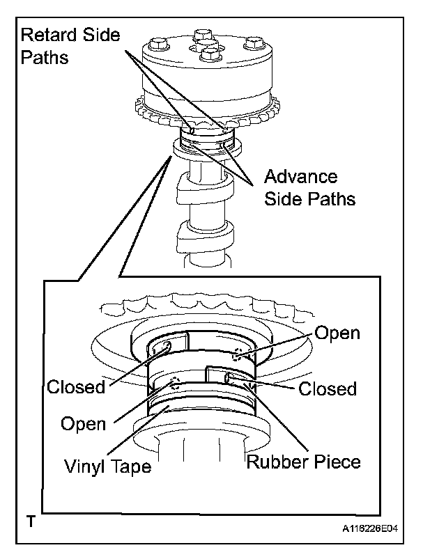
(b) Release the lock pin.
(1) Cover the 4 oil paths of the cam journal with tape as shown in the illustration.
HINT: One of the 2 grooves located on the cam journal is for retarding cam timing (upper) and the other is for advancing cam timing (lower). Each groove has 2 oil paths. Plug one of the oil paths for each groove with a piece of rubber before wrapping the cam journal with the tape.
(2) Puncture the tape covering the advance oil path and the retard oil path on the opposite side from the advance oil path.
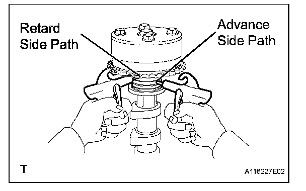
(3) Apply air at about 150 kPa (1.5 kgf*cm2) pressure into the 2 broken paths (the advance side path and the retard side path).
NOTICE: Cover the paths with a shop rag or piece of cloth to prevent oil splashes.
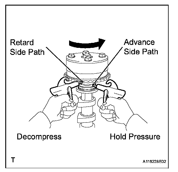
(4) Confirm that the camshaft timing gear assembly revolves in the timing advance direction when the air pressure on the timing retard path is reduced.
HINT: The lock pin is released and the camshaft timing gear revolves in the advance direction.
(5) When the camshaft timing gear reaches the most advanced position, release the air pressure on the timing retard side path, and then release the air pressure on the timing advance side path.
NOTICE: Camshaft timing gear assembly occasionally shifts to the retard side abruptly if the air pressure on the advance side path is released first. This often results in breakage of the lock pin.
(c) Check that the revolution is smooth.
(1) Rotate the valve timing assembly back and forth several times, except where the lock pin meets it at the most retarded angle. Check the movable range and that it rotates smoothly.
Standard: Smooth movable range is about 22.5°
NOTICE: Perform this check by hand, instead of using air pressure.
(d) Check that the gear locks in the most retarded position.
(1) Confirm that the camshaft timing gear assembly is locked in the most retarded position.
2. INSPECT CHAIN SUB-ASSEMBLY
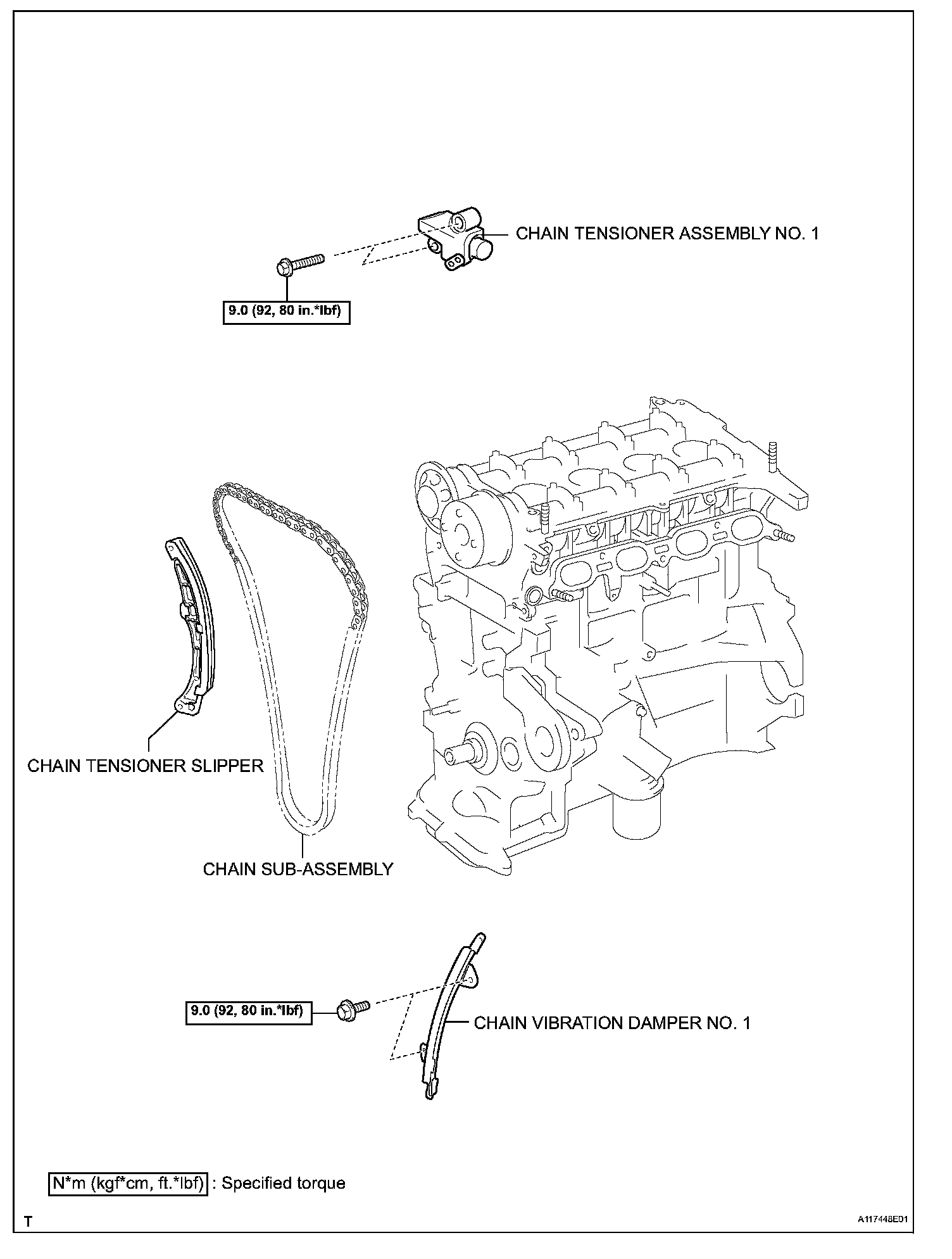
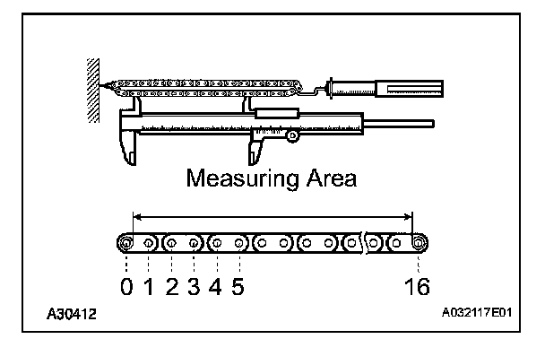
(a) Using a spring scale, apply 140 N (14.3 kgf, 31.5 lb) to the timing chain and measure its length.
Maximum chain elongation: 123.2 mm (4.850 in.)
If the elongation is greater than the maximum, replace the chain.
HINT: Perform the same measurement at 3 or more random places and calculate the average length.
3. INSPECT CHAIN TENSIONER ASSEMBLY NO. 1
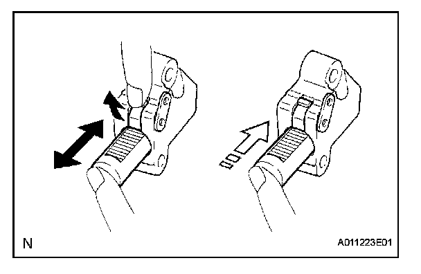
(a) Check that the plunger moves smoothly when the ratchet pawl is raised with your finger.
(b) Release the ratchet pawl and check that the plunger is locked in place by the ratchet pawl and does not move when pushed with your finger.
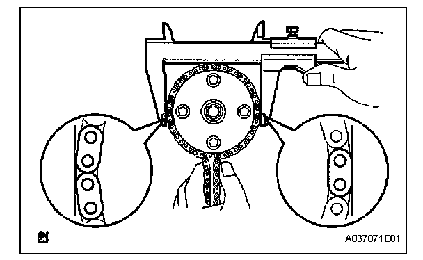
4. INSPECT CAMSHAFT TIMING GEAR ASSEMBLY
(a) Wrap the chain around the timing sprocket.
(b) Using vernier calipers, measure the diameter of the timing gear with the chain.
Minimum gear diameter (with chain): 96.2 mm (3.787 in.)
If the diameter is less than the minimum, replace the camshaft timing gear.
NOTICE: Make sure that the vernier calipers are in contact with the chain link when measuring.
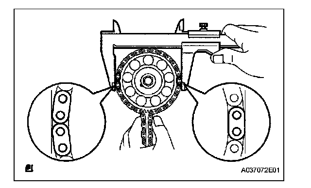
5. INSPECT CAMSHAFT TIMING SPROCKET
(a) Wrap the chain around the timing sprocket.
(b) Using vernier calipers, measure the diameter of the timing gear with the chain.
Minimum gear diameter (with chain): 96.2 mm (3.787 in.)
If the diameter is less than the minimum, replace the camshaft timing sprocket.
NOTICE: Make sure that the vernier calipers are in contact with the chain link when measuring.
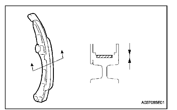
6. INSPECT CHAIN TENSIONER SLIPPER
(a) Check the chain tensioner slipper.
Minimum thickness: 1.0 mm (0.039 in.)
If the thickness is less than the minimum, replace the chain tensioner slipper.
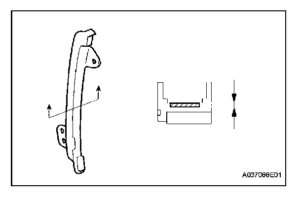
7. INSPECT CHAIN VIBRATION DAMPER NO. 1
(a) Check the vibration damper.
Minimum thickness: 1.0 mm (0.039 in.)
If the thickness is less than the minimum, replace the chain vibration damper.
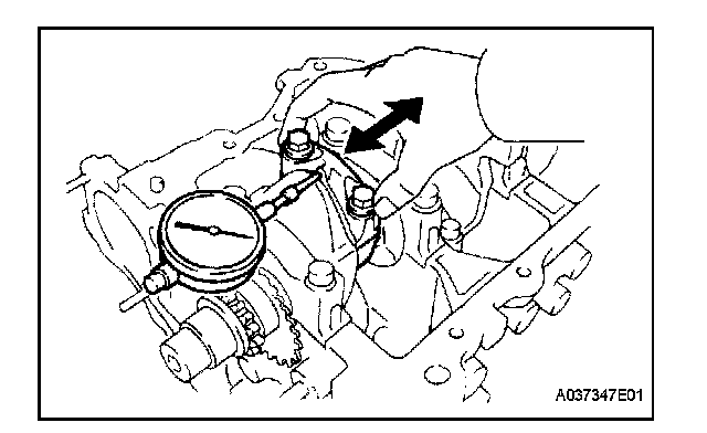
8. INSPECT CONNECTING ROD THRUST CLEARANCE
(a) Using a dial indicator, measure the thrust clearance while moving the connecting rod back and forth.
Standard thrust clearance: 0.16 to 0.36 mm (0.0063 to 0.0142 in.)
Maximum thrust clearance: 0.36 mm (0.0142 in.)