Part 2
ENGINE UNITCOMPONENTS (Part 1):
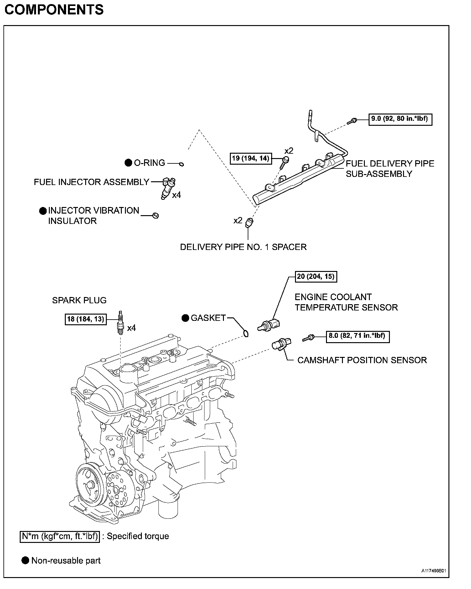
COMPONENTS (Part 2):
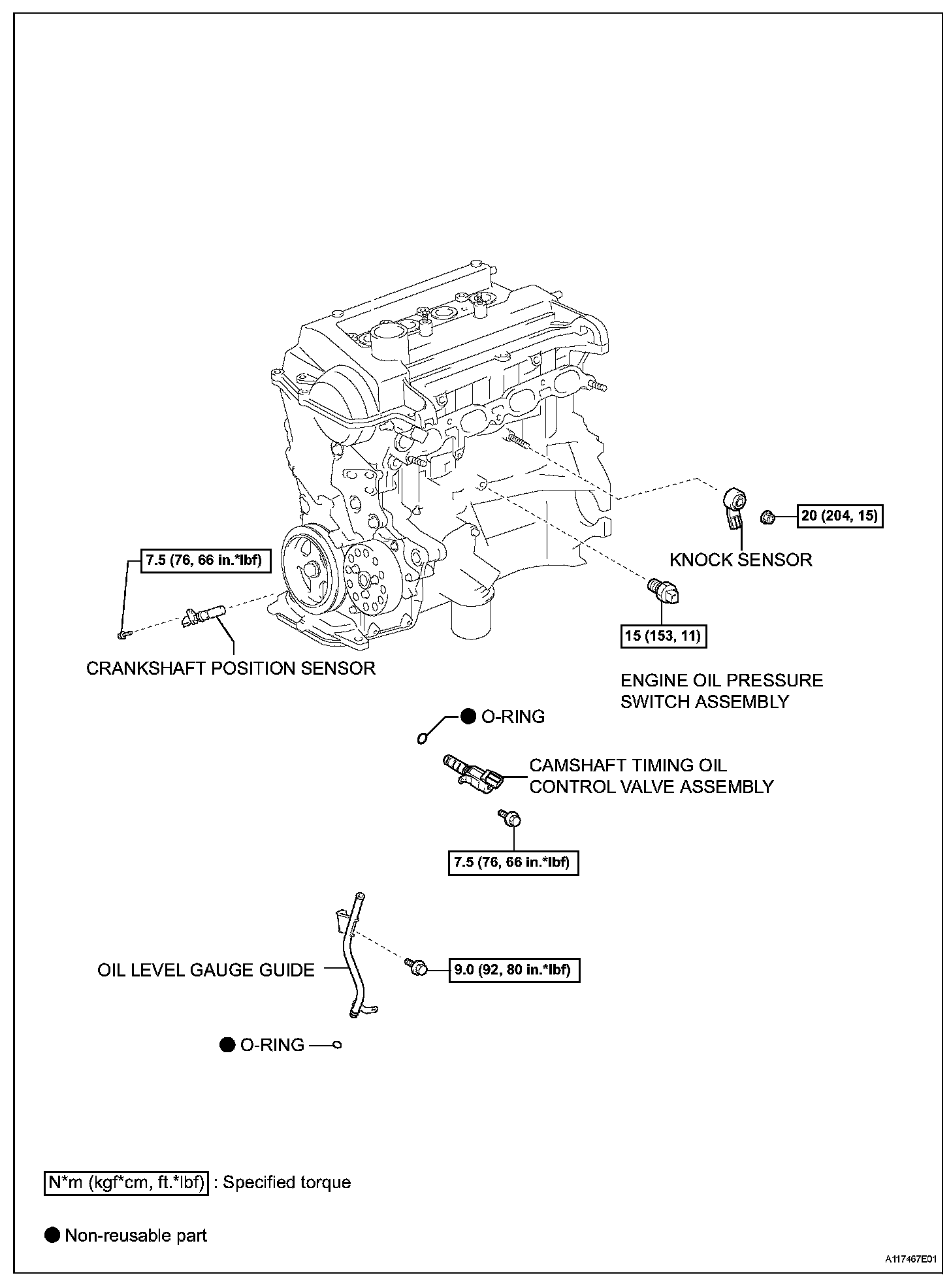
COMPONENTS (Part 3):
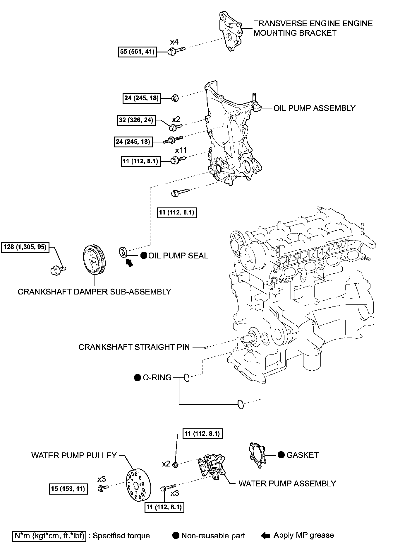
COMPONENTS (Part 4):
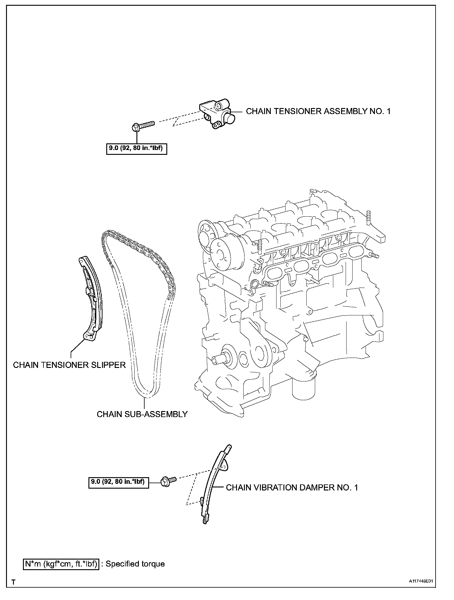
COMPONENTS (Part 5):
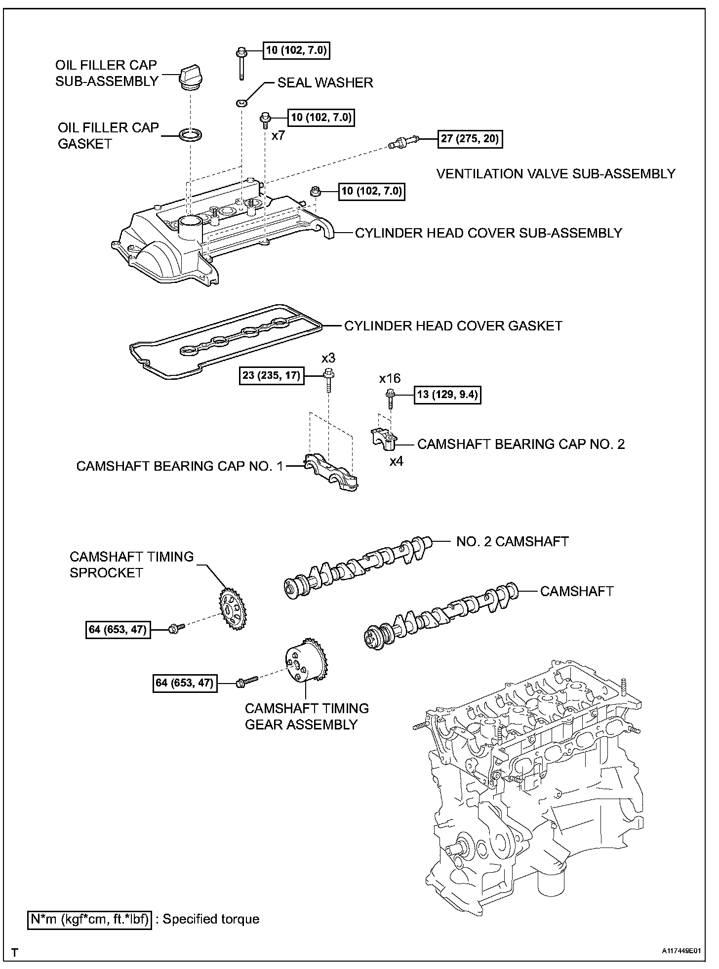
COMPONENTS (Part 6):
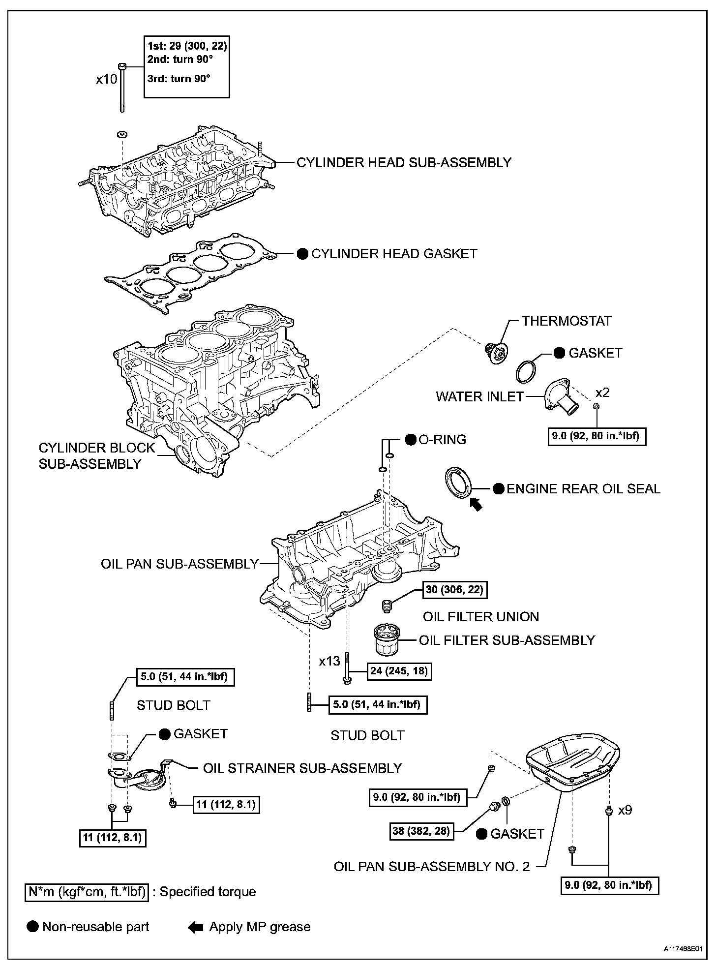
COMPONENTS (Part 7):

COMPONENTS (Part 8):
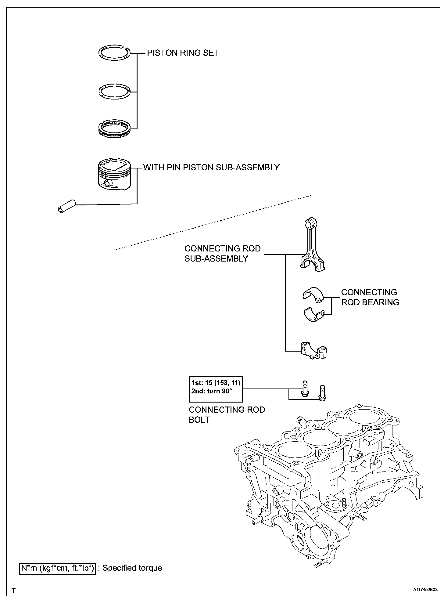
INSPECTION Continued
9. INSPECT CONNECTING ROD OIL CLEARANCE
(a) Check that the matchmarks on the connecting rod and cap are aligned to ensure correct reassembly.
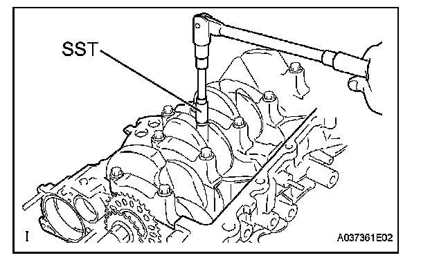
(b) Using SST, remove the 2 connecting rod cap bolts.
SST 09205-16010
(c) Clean the crank pin and bearing.
(d) Check the crank pin and bearing for pitting and scratches.
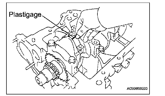
(e) Lay a strip of Plastigage across the crank pin.
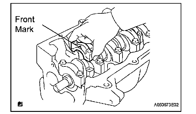
(f) Make sure that the connecting rod and its cap are in the correct combination and that the front mark of the cap is facing in the correct mounting orientation, then install the cap onto the connecting rod.
(g) Apply a light coat of engine oil to the threads of the connecting rod cap bolts.
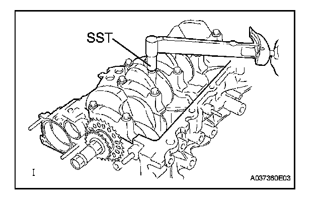
(h) Using SST, tighten the bolts in several steps to the specified torque.
SST 09205-16010
Torque: 15 N*m (153 kgf*cm, 11 ft.*lbf)
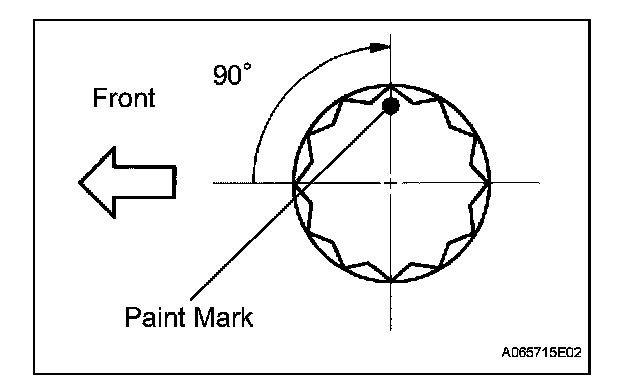
(i) Mark the front of the connecting cap bolts with paint.
(j) Retighten the cap bolts by 90° as shown in the illustration.
NOTICE: Do not turn the crankshaft.
(k) Remove the 2 bolts, connecting rod cap and lower bearing.
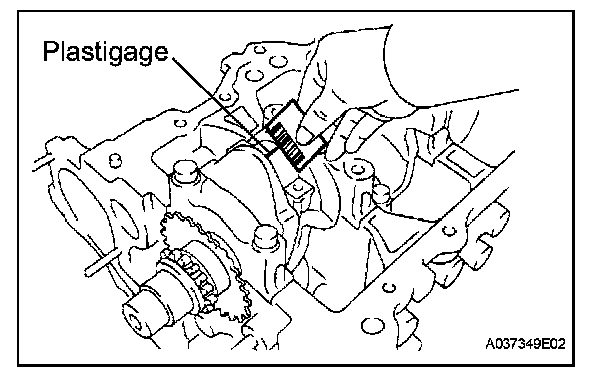
(l) Measure the Plastigage at its widest point.
Standard oil clearance: 0.012 to 0.038 mm (0.00047 to 0.00015 in.)
Maximum oil clearance: 0.058 mm (0.0028in.)
NOTICE: Completely remove the Plastigage after the measurement.
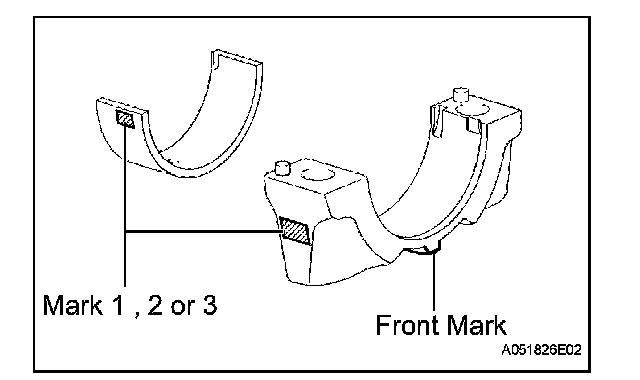
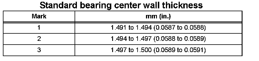
(m) When replacing a bearing, replace it with one with the same number as marked on the connecting rod. There are 3 sizes of standard bearings, marked 1, 2 and 3 accordingly.
Standard bearing center wall thickness:
10. INSPECT CRANKSHAFT THRUST CLEARANCE
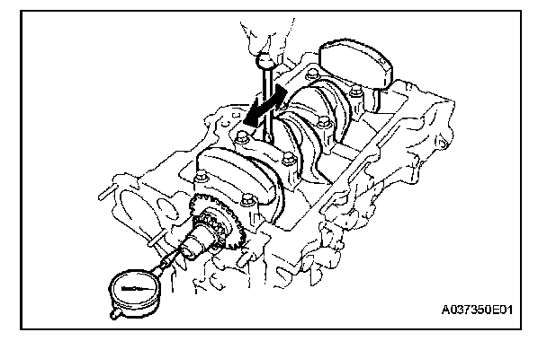
(a) Using a dial indicator, measure the thrust clearance while moving the crankshaft back and forth with a screwdriver.
Standard thrust clearance: 0.09 to 0.19 mm (0.0035 to 0.0075 in.)
Maximum thrust clearance: 0.30 mm (0.0118 in.)
If the thrust clearance is greater than the maximum, replace the thrust washers as a set. Check the crankshaft and block for wear. Repair or replace the parts if necessary.
HINT: Thrust washer thickness: 2.43 to 2.48 mm (0.0957 to 0.976 in.)
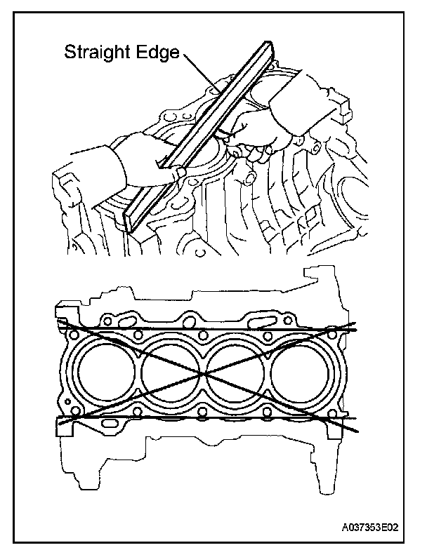
11. INSPECT CYLINDER BLOCK FOR WARPAGE
(a) Using a precision straight edge and feeler gauge, measure the warpage of the surface which is in contact with the cylinder head gasket.
Maximum warpage: 0.05 mm (0.0020 in.)
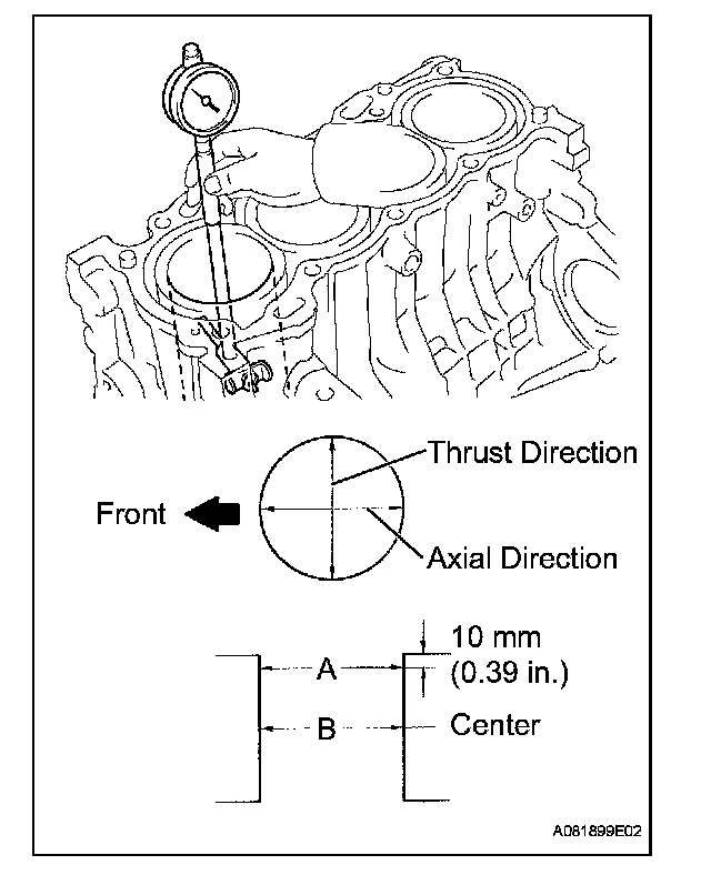
12. INSPECT CYLINDER BORE
(a) Using a cylinder gauge, measure the cylinder bore diameter at positions A and B in both the thrust and axial directions.
Standard Inside diameter: 75.000 to 75.013 mm (2.9528 to 2.9533 in.)
(b) Calculate the difference between the maximum diameter and the minimum diameter of the 4 measured values.
Difference limit: 0.10 mm (0.0039 in.)
If the difference is greater than the limit, replace the cylinder block.
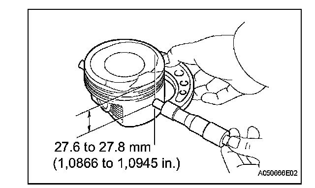
13. INSPECT WITH PIN PISTON SUB-ASSEMBLY
(a) Using a micrometer, measure the piston diameter at a right angle to the piston pin center line, and at the position 27.6 to 27.8 mm (1.0866 to 1.0945 in.) from the top of the piston head.
Piston diameter: 74.935 to 74.945 mm (2.9502 to 2.9506 in.)
(b) Using a caliper gauge, measure the piston pin hole diameter.
Piston pin hole diameter: 18.013 to 18.016 mm (0.7092 to 0.7093 in.) at 20°C (68°F)
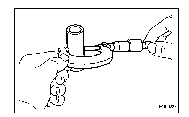
(c) Using a micrometer, measure the piston pin diameter.
Piston pin diameter: 18.001 to 18.004 mm (0.7087 to 0.7088 in.)
(d) Subtract the piston pin diameter measurement from the piston pin hole diameter measurement to calculate the oil clearance.
Standard oil clearance: 0.009 to 0.015 mm (0.0004 to 0.0006 in.)
Maximum oil clearance: 0.050 mm (0.0020 in.)
If necessary, replace the piston and piston pin together.
14. INSPECT PISTON CLEARANCE
(a) Subtract the piston diameter measurement from the cylinder bore diameter measurement.
Standard oil clearance: 0.045 to 0.068 mm (0.0018 to 0.0027 in.)
Maximum oil clearance: 0.08 mm (0.0032 in.)
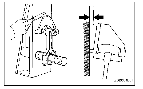
15. INSPECT CONNECTING ROD SUB-ASSEMBLY
(a) Using a rod aligner and feeler gauge, check the connecting rod alignment.
(1) Check for misalignment.
Maximum misalignment: 0.05 mm (0.0020 in.) per 100 mm (3.94 in.)
If the misalignment is greater than the maximum, replace the connecting rod assembly.
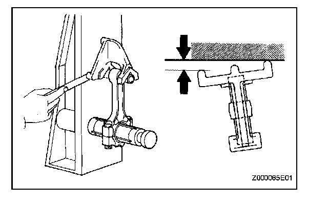
(2) Check for twist.
Maximum twist: 0.05 mm (0.0020 in.) per 100 mm (3.94 in.)
If the twist is greater than the maximum, replace the connecting rod assembly.