Part 3
ENGINE UNITCOMPONENTS (Part 1):
COMPONENTS (Part 2):
COMPONENTS (Part 3):
COMPONENTS (Part 4):
COMPONENTS (Part 5):
COMPONENTS (Part 6):
COMPONENTS (Part 7):

COMPONENTS (Part 8):
REASSEMBLY Continued
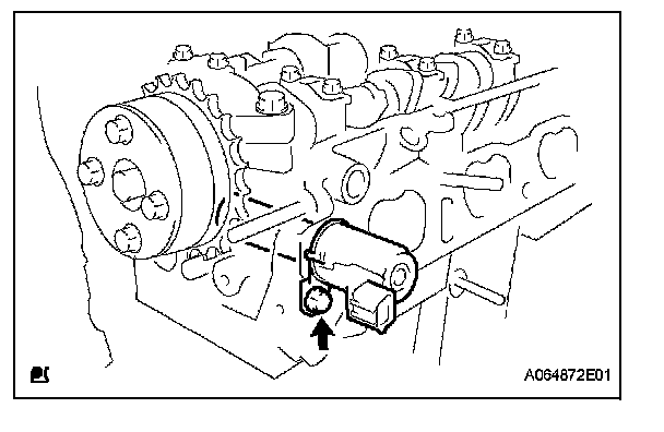
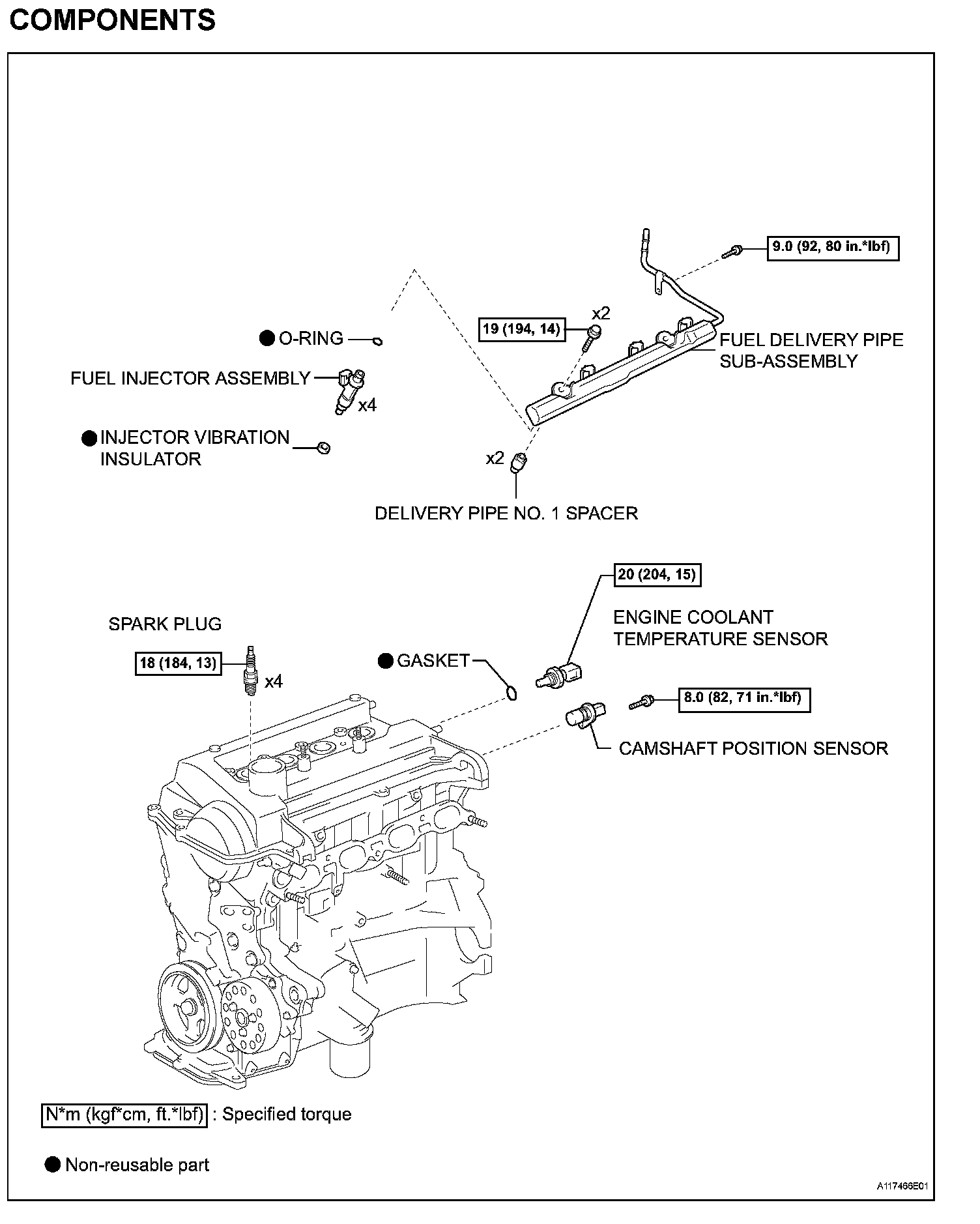
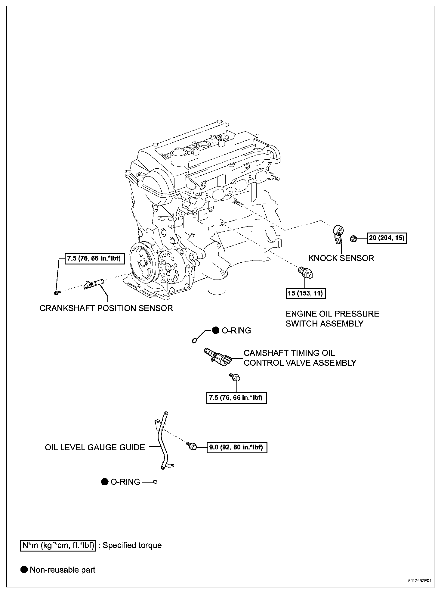
41. INSTALL CAMSHAFT TIMING OIL CONTROL VALVE ASSEMBLY
(a) Apply a light coat of engine oil to a new O-ring, and install it onto the camshaft timing oil control valve.
(b) Install the camshaft timing oil control valve with the bolt.
Torque: 7.5 N*m (76 kgf*cm, 66 in.*lbf)
NOTICE: Do not twist the O-ring.
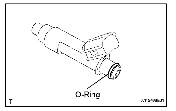
42. INSTALL FUEL INJECTOR ASSEMBLY
(a) Apply a light coat of gasoline or spindle oil to new O-rings, then install one onto each fuel injector.
(b) Apply a light coat of gasoline or spindle oil to the contact surfaces of the fuel delivery pipe and the O-ring of the fuel injector.
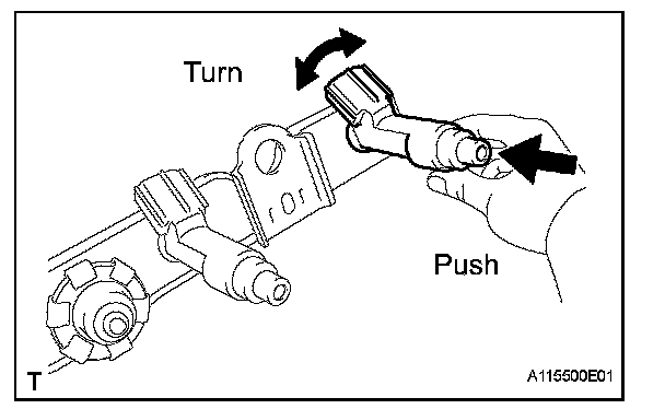
(c) While turning the fuel injector left and right, install it onto the fuel delivery pipe.
NOTICE:
^ Do not twist the O-ring.
^ After installing the fuel injectors, check that they turn smoothly. If not, replace the O-ring with a new one.
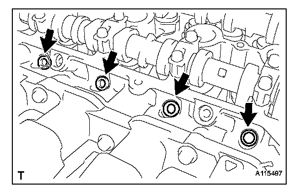
43. INSTALL INJECTOR VIBRATION INSULATOR
(a) Install 4 new injector vibration insulators onto the cylinder head.
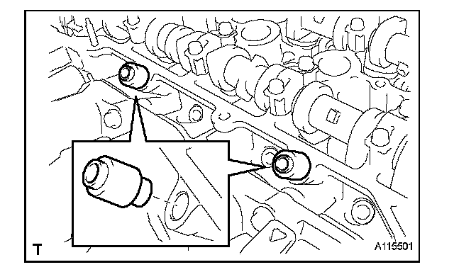
44. INSTALL DELIVERY PIPE NO. 1 SPACER
(a) Install the 2 delivery pipe No. 1 spacers onto the cylinder head.
NOTICE: Install delivery pipe No. 1 spacer in the correct direction.
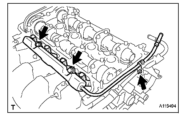
45. INSTALL FUEL DELIVERY PIPE SUB-ASSEMBLY
(a) Provisionally install the fuel delivery pipe subassembly and 4 fuel injectors with the 3 bolts.
NOTICE:
^ Do not drop the fuel injectors when installing the fuel delivery pipe sub-assembly.
^ Check that the fuel injectors rotate smoothly after installing the fuel delivery pipe subassembly.
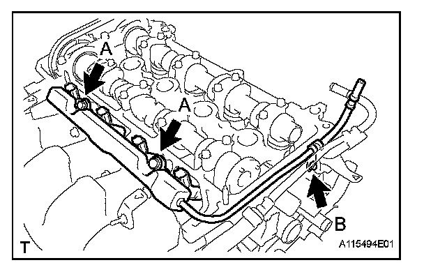
(b) Tighten the 3 bolts to the specified torque.
Torque: 19 N*m (194 kgf*cm, 14 ft.*lbf) for bolt A
9.0 N*m (92 kgf*cm, 80 in.*lbf) for bolt B
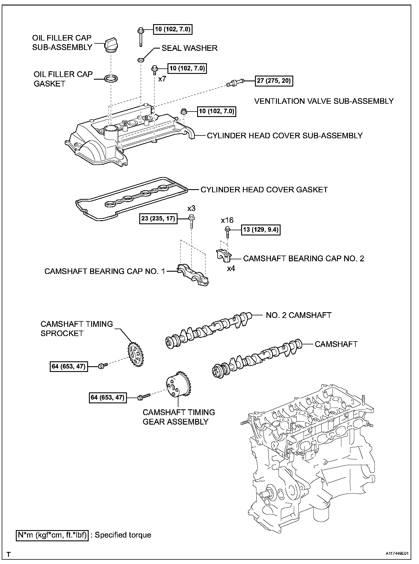
46. INSTALL CYLINDER HEAD COVER SUB-ASSEMBLY
(a) Install the gasket onto the cylinder head cover.
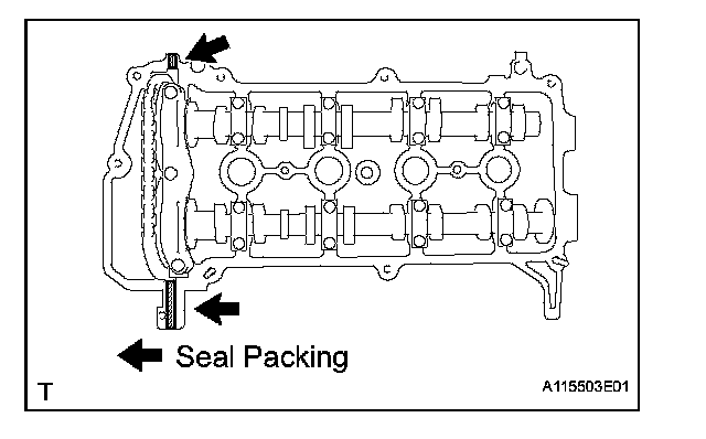
(b) Apply seal packing to the cylinder head, as shown in the illustration.
Seal Packing: Toyota Genuine Seal Packing Black, Three Bond 1207B or Equivalent
NOTICE:
^ Remove any oil from the contact surface.
^ Install the cylinder head cover sub-assembly within 3 minutes of applying the seal packing.
^ Do not start engine for at least 2 hours after the installation.
(c) Install the cylinder head cover sub-assembly with the 9 bolts, 2 nuts and 2 seal washers.
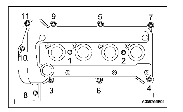
(d) Tighten the 9 bolts and 2 nuts in the sequence shown in the illustration.
Torque: 10 N*m (102 kgf*cm, 7.0 ft.*lbf)
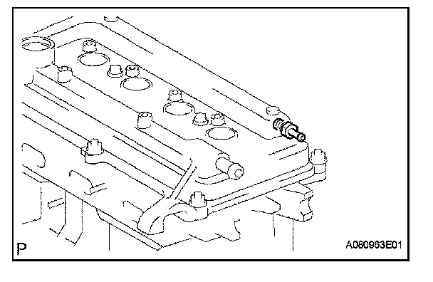
47. INSTALL VENTILATION VALVE SUB-ASSEMBLY
(a) Install the ventilation valve onto the cylinder head cover.
Torque: 27 N*m (275 kgf*cm, 20 ft.*lbf)
48. INSTALL OIL LEVEL GAUGE GUIDE
(a) Apply engine oil to a new O-ring.
(b) Install the oil level gauge guide with the bolt.
Torque: 9.0 N*m (92 kgf*cm, 80 in.*lbf)
49. INSTALL CRANKSHAFT POSITION SENSOR
(a) Apply a light coat of engine oil to the O-ring on the crankshaft position sensor.
NOTICE: If the O-ring is damaged, replace the crankshaft position sensor.
(b) Install the crankshaft position sensor with the bolt.
Torque: 7.5 N*m (76 kgf*cm, 66 in.*lbf)
50. INSTALL OIL FILLER CAP GASKET
(a) Install the oil filler cap gasket onto the oil filler cap.
51. INSTALL OIL FILLER CAP SUB-ASSEMBLY
(a) Install the oil filler cap onto the cylinder head cover.
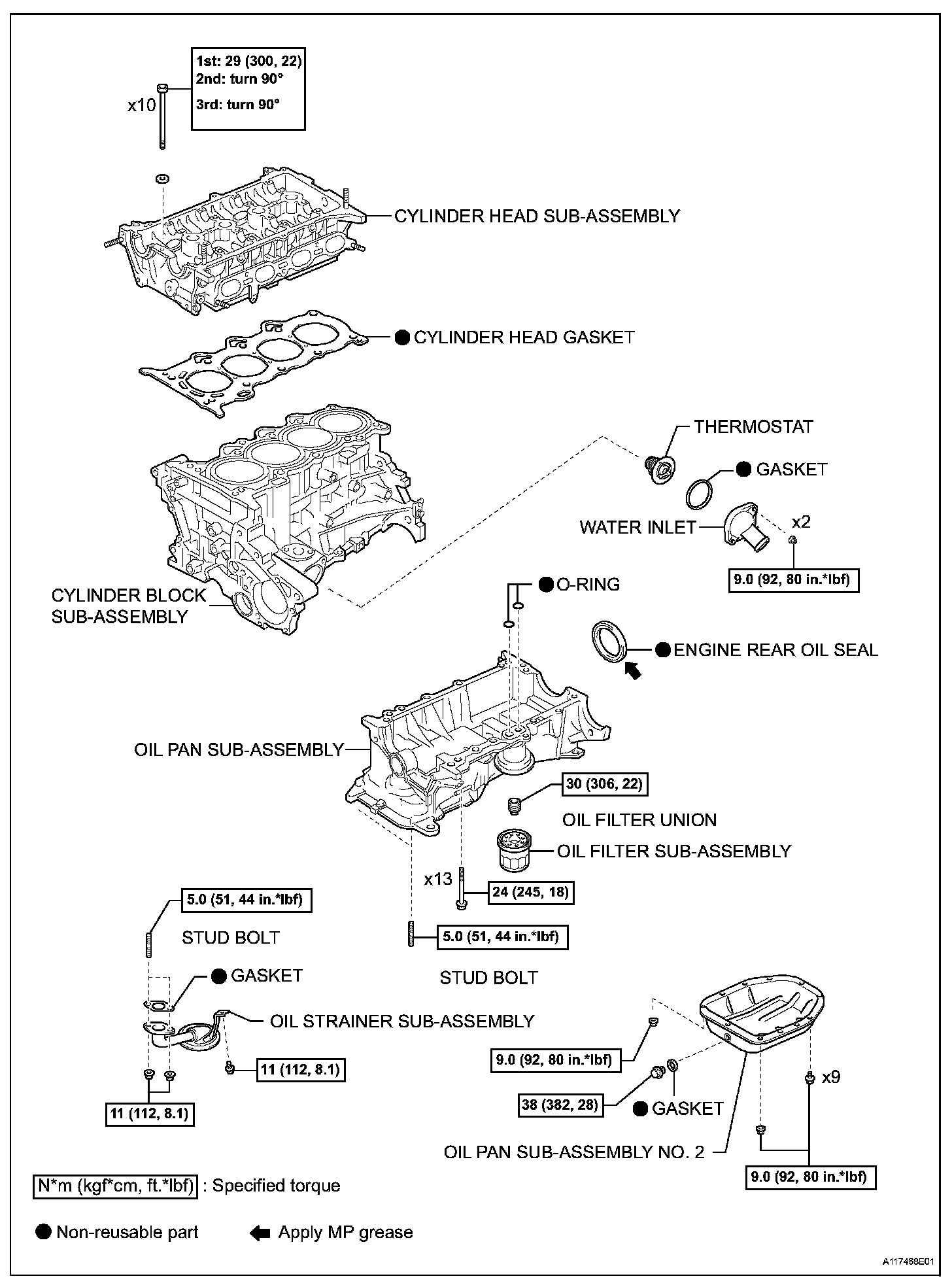
52. INSTALL THERMOSTAT
(a) Install a new gasket onto the thermostat.
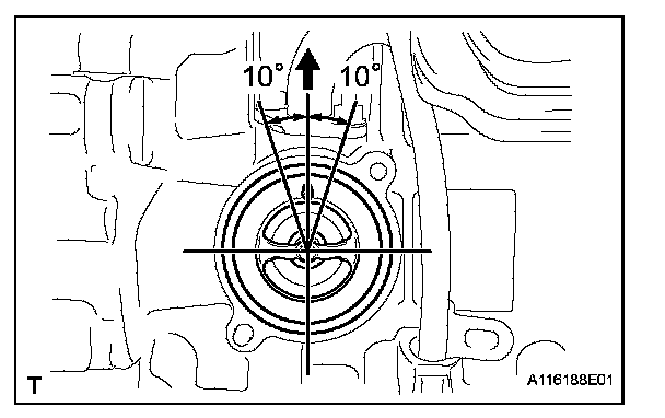
(b) Install the thermostat with the jiggle valve facing upward.
HINT: The jiggle valve may be set within 10° either side as shown in the illustration.
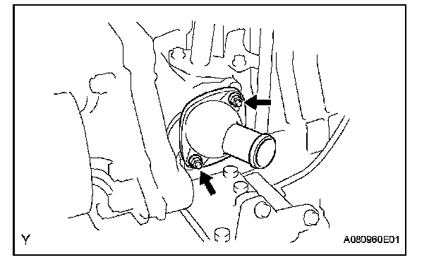
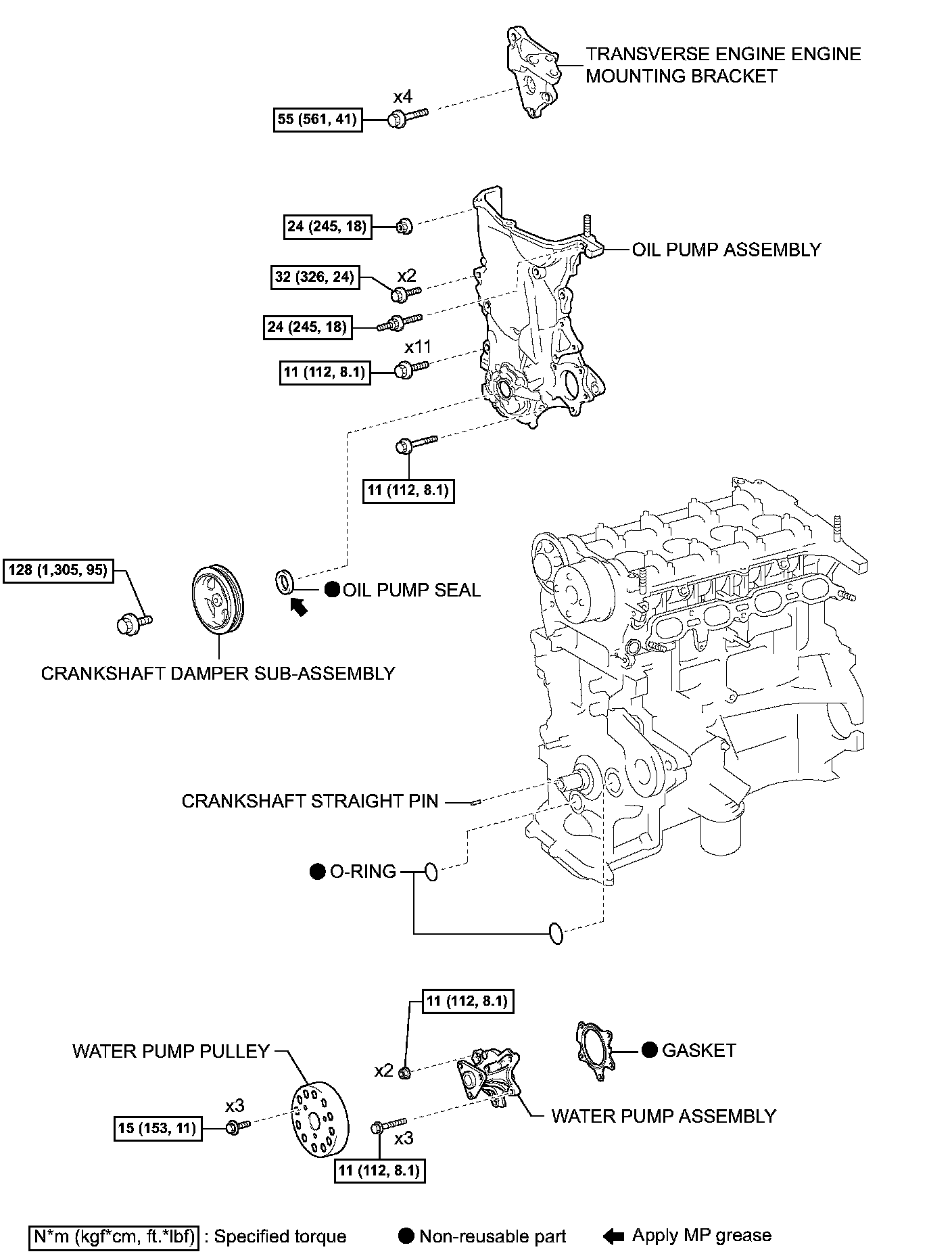
53. INSTALL WATER INLET
(a) Install the water inlet with the 2 nuts.
Torque: 9.0 N*m (92 kgf*cm, 80 in.*lbf)
54. INSTALL ENGINE COOLANT TEMPERATURE SENSOR
(a) Provisionally install the engine coolant temperature sensor through a new gasket.
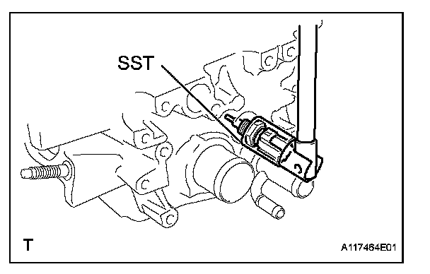
(b) Using SST, tighten the engine coolant temperature sensor.
SST 09817-33190
Torque: 20 N*m (204 kgf*cm, 15 ft.*lbf)
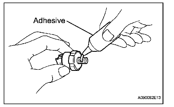
55. INSTALL ENGINE OIL PRESSURE SWITCH ASSEMBLY
(a) Apply adhesive to the end 2 or 3 threads of the oil pressure switch.
Adhesive: Toyota Genuine Adhesive 1324, Three Bond 1324 or Equivalent
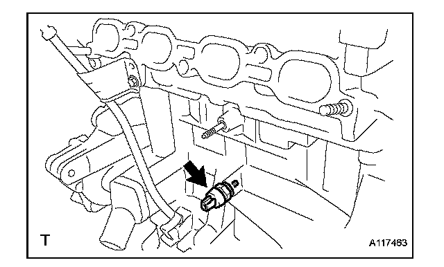
(b) Using a 24 mm deep socket wrench, install the oil pressure switch.
Torque: 15 N*m (153 kgf*cm, 11 ft.*lbf)
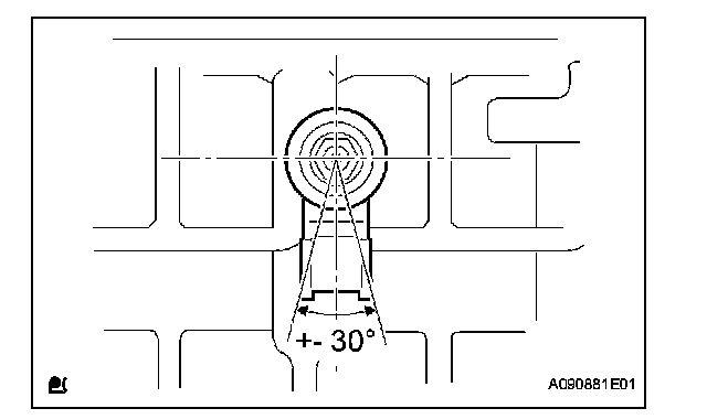
56. INSTALL KNOCK SENSOR
(a) Install the knock sensor with the nut as shown in the illustration.
Torque: 20 N*m (204 kgf*cm, 15 ft.*lbf)
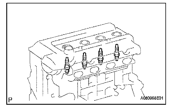
57. INSTALL SPARK PLUG
(a) Using a spark plug wrench, install the spark plugs.
Torque: 18 N*m (184 kgf*cm, 13 ft.*lbf)