Diagnosis System
DIAGNOSIS SYSTEM1. DESCRIPTION
(a) When troubleshooting OBD II vehicles, the only difference from the usual troubleshooting procedure is to connect an intelligent tester (complying with SAE J1987) to the vehicle, and read off various data output by the vehicle's ECM.
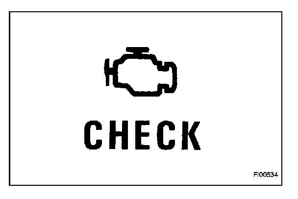
(b) OBD II regulations require that the vehicle's on-board computer illuminate the Malfunction Indicator Lamp (MIL) on the instrument panel when the computer detects a malfunction in the computer itself or in the drive system components which affect the vehicle emissions. In addition to illuminating the MIL when a malfunction is detected, the applicable DTCs prescribed by SAE J2012 are recorded in the ECM memory.
If the malfunction does not occur in 3 consecutive trips, the MIL goes off but the DTCs remain in the ECM memory.
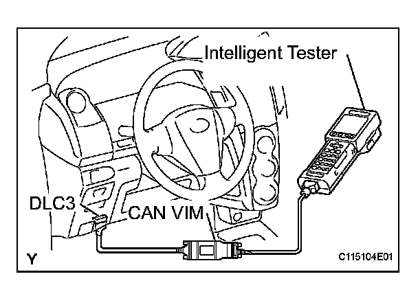
(c) To check the DTCs, connect the intelligent tester to the DLC3 of the vehicle. The intelligent tester also enables you to erase the DTCs and check freeze frame data and various forms of engine data (For operating instructions, see the instruction book).
(d) The DTCs include SAE controlled codes and manufacturer controlled codes. SAE controlled codes must be set as prescribed by the SAE, while manufacturer controlled codes can be set freely by the manufacturer within the prescribed limits.
(e) The diagnosis system operates in normal mode during normal vehicle use. In normal mode, 2-trip detection logic is used to ensure accurate detection of malfunctions. Check mode is also available to technicians as an option. In check mode, 1-trip detection logic is used for simulating malfunction symptoms and increasing the system's ability to detect malfunctions, including intermittent malfunctions.
(f) 2-trip detection logic: When a malfunction is first detected, the malfunction is temporarily stored in the ECM memory (1st trip). If the ignition switch is turned off and then turned to the ON position again, and same malfunction is detected again, the MIL illuminates.
(g) Freeze frame data records the engine conditions, such as fuel system, calculated load, engine coolant temperature, fuel trim, engine speed and vehicle speed when a malfunction is detected. When troubleshooting, freeze frame data can help determine if the vehicle was running or stopped, if the engine was warmed up or not, if the air/fuel ratio was lean or rich, and other data from the time the malfunction occurred.
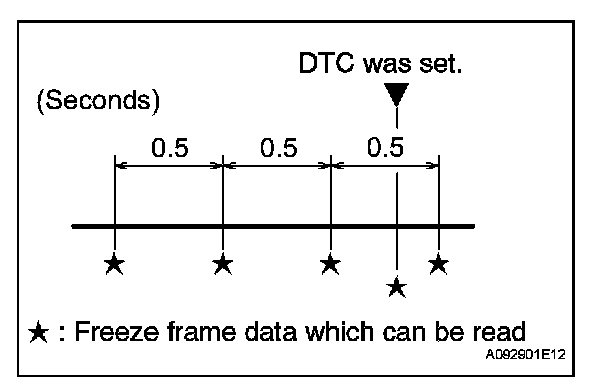
(h) The intelligent tester records freeze frame data in five different instances: 1) 3 times before the DTC is set, 2) once when the DTC is set, and 3) once after the DTC is set. These data can be used to simulate the vehicle's conditions around the time when the malfunction occurred. The data may help find the cause of the malfunction, or judge if the DTC is being caused by a temporary malfunction or not.
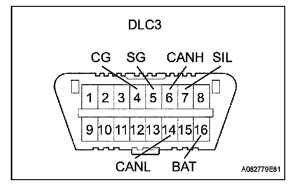
2. INSPECT DLC3
(a) The ECM uses ISO 15765-4 for communication. The terminal arrangement of the DLC3 complies with SAE J1962 and matches the ISO 15765-4 format.
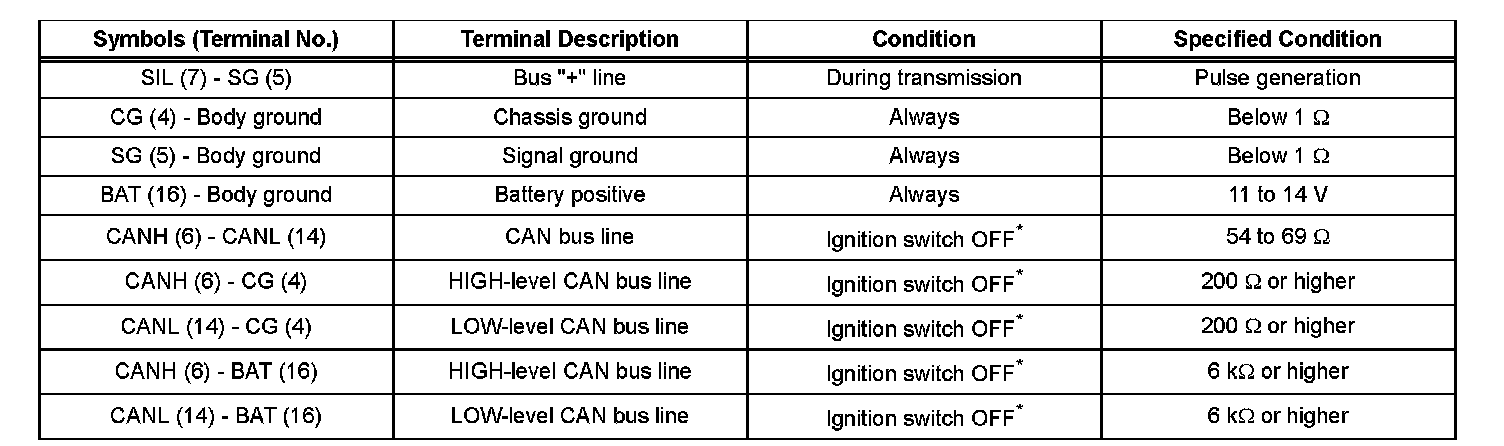
NOTICE: *: Before measuring the resistance, leave the vehicle as is for at least 1 minute and do not operate the ignition switch, any other switches or the doors.
If the result is not as specified, the DLC3 may have a malfunction. Repair or replace the harness and connector.
HINT: If your display shows UNABLE TO CONNECT TO VEHICLE when you have connected the cable of the intelligent tester to the DLC3, turned the ignition switch to the ON position and operated the tester, there is a problem with the vehicle or the tester.
^ If the communication is normal when the tester is connected to another vehicle, inspect the DLC3 on the original vehicle.
^ If the communication is still impossible when the tester is connected to another vehicle, the problem is probably in the tester itself. Consult the Service Department listed in the tester's instruction manual.
3. CHECK BATTERY VOLTAGE
(a) Measure the battery voltage.
Standard voltage: 11 to 14 V
If the voltage is below 11 V, replace the battery before proceeding.
4. CHECK MIL
(a) The MIL comes on when the ignition switch is turned to the ON position and the engine is not running.
HINT: If the MIL does not light up, troubleshoot the combination meter.
(b) When the engine is started, the MIL should go off. If the lamp remains on, it means that the diagnosis system has detected a malfunction or abnormality in the system.