Display Signal Circuit Between Television Display Assembly and Navigation Receiver Assembly
AUDIO / VIDEO: REAR SEAT ENTERTAINMENT SYSTEM: Display Signal Circuit between Television Display Assembly and Navigation Receiver Assembly
Display Signal Circuit between Television Display Assembly and Navigation Receiver Assembly
DESCRIPTION
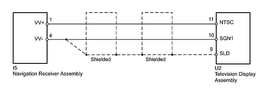
This circuit sends a display signal from the television display assembly to the navigation receiver assembly.
WIRING DIAGRAM
INSPECTION PROCEDURE
PROCEDURE
1. CHECK HARNESS AND CONNECTOR (TELEVISION DISPLAY ASSEMBLY - NAVIGATION RECEIVER ASSEMBLY)
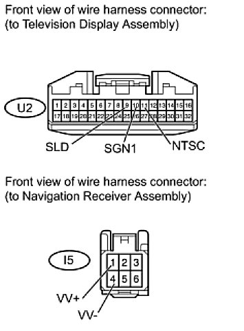
(a) Disconnect the U2 television display assembly connector.
(b) Disconnect the I5 navigation receiver assembly connector.
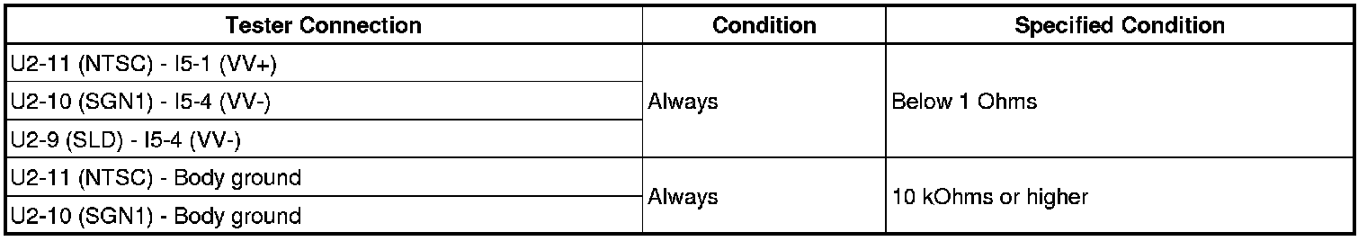
(c) Measure the resistance according to the value(s) in the table below.
Standard Resistance:
(d) Reconnect the television display assembly connector.
(e) Reconnect the navigation receiver assembly connector.
NG -- REPAIR OR REPLACE HARNESS OR CONNECTOR
OK -- Continue to next step.
2. INSPECT TELEVISION DISPLAY ASSEMBLY (NTSC SIGNAL)
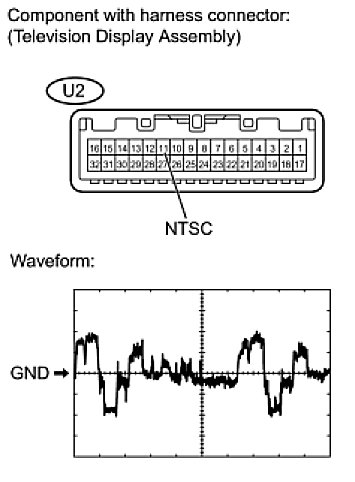
(a) Using an oscilloscope, check the waveform.
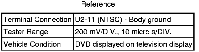
OK:
Waveform is as shown in the illustration.
NG -- REPLACE TELEVISION DISPLAY ASSEMBLY
OK -- PROCEED TO NEXT CIRCUIT INSPECTION SHOWN IN PROBLEM SYMPTOMS TABLE