Combination Meter ECU Communication Stop Mode
NETWORKING: CAN COMMUNICATION SYSTEM: Combination Meter ECU Communication Stop Mode
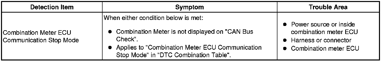
Combination Meter ECU Communication Stop Mode
DESCRIPTION
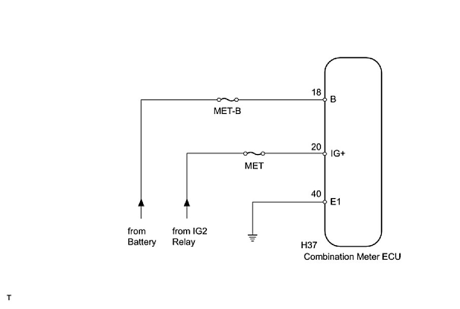
WIRING DIAGRAM
INSPECTION PROCEDURE
HINT: Operating the ignition switch, any switches or any doors triggers related ECU and sensor communication with the CAN, which causes resistance variation.
PROCEDURE
1. CHECK HARNESS AND CONNECTOR (COMBINATION METER ECU - BATTERY AND BODY GROUND)
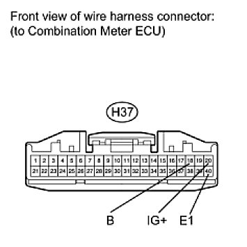
(a) Disconnect the H37 combination meter ECU connector.
(b) Measure the resistance according to the value(s) in the table below.
Standard Resistance:

(c) Measure the voltage according to the value(s) in the table below.
Standard Voltage:

NG -- REPAIR OR REPLACE HARNESS OR CONNECTOR
OK -- REPLACE COMBINATION METER ASSEMBLY