Power Steering ECU Communication Stop Mode
NETWORKING: CAN COMMUNICATION SYSTEM: Power Steering ECU Communication Stop Mode
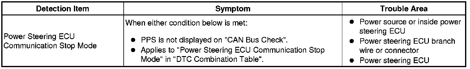
Power Steering ECU Communication Stop Mode
DESCRIPTION
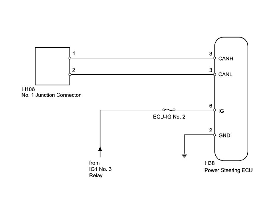
WIRING DIAGRAM
INSPECTION PROCEDURE
PROCEDURE
1. DISCONNECT CABLE FROM NEGATIVE BATTERY TERMINAL
(a) Disconnect the cable from the negative (-) battery terminal before measuring the resistances of the main wire and the branch wire.
CAUTION: Wait at least 90 seconds after disconnecting the cable from the negative (-) battery terminal to disable the SRS system.
NEXT -- Continue to next step.
2. CHECK FOR OPEN IN CAN BUS WIRE (POWER STEERING ECU BRANCH WIRE)
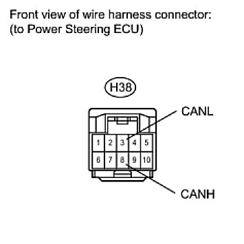
(a) Disconnect the H38 power steering ECU connector.
(b) Measure the resistance according to the value(s) in the table below.
Standard Resistance:

NG -- REPAIR OR REPLACE POWER STEERING ECU BRANCH WIRE OR CONNECTOR (CANH, CANL)
OK -- Continue to next step.
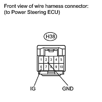
3. CHECK HARNESS AND CONNECTOR (POWER STEERING ECU - BATTERY AND BODY GROUND)
(a) Reconnect the cable to the negative (-) battery terminal-.
(b) Disconnect the H38 power steering ECU connector.
(c) Measure the resistance according to the value(s) in the table below.
Standard Resistance:

(d) Measure the voltage according to the value(s) in the table below.
Standard Voltage:

NG -- REPAIR OR REPLACE HARNESS OR CONNECTOR
OK -- REPLACE POWER STEERING ECU