Engine Switch Indicator Circuit
2GR-FE STARTING: SMART KEY SYSTEM: Engine Switch Indicator Circuit
Engine Switch Indicator Circuit
DESCRIPTION
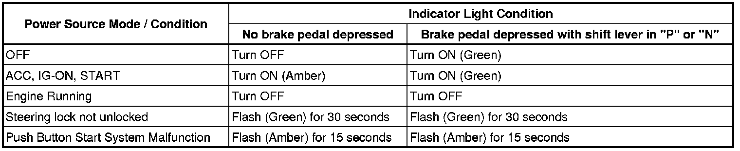
Engine start conditions or system malfunctions can be checked by the status of the engine switch indicator light.
Engine switch indicator light condition:
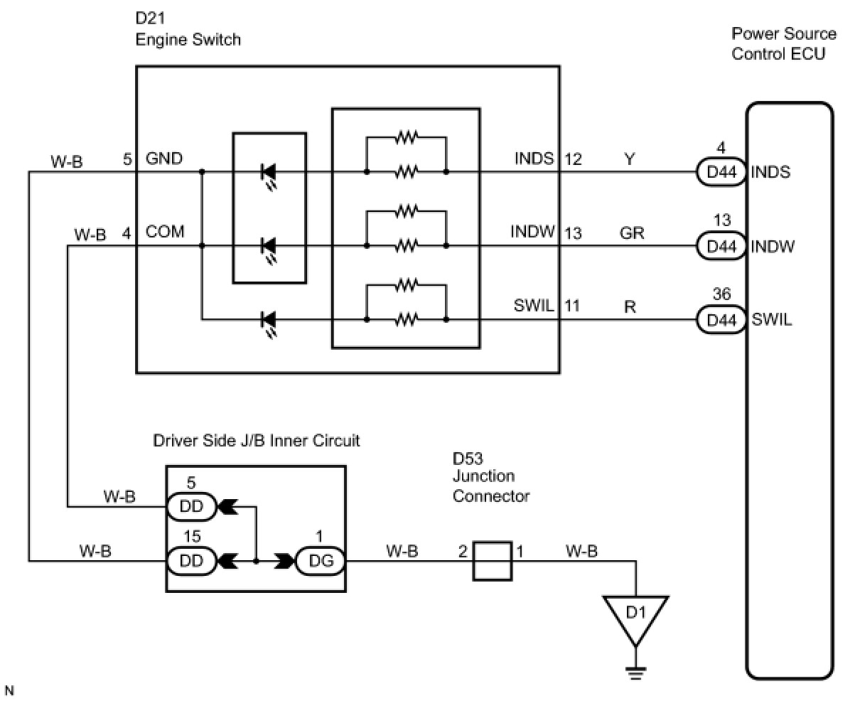
WIRING DIAGRAM
INSPECTION PROCEDURE
PROCEDURE
1. INSPECT ENGINE SWITCH
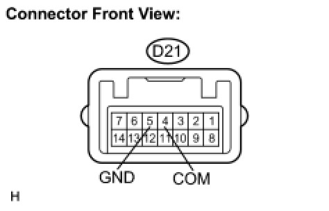
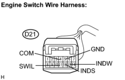
(a) Disconnect the D21 switch connector.
(b) Connect the positive (+) lead to terminal "A" and the negative (-) lead to terminal "B" of the engine switch.
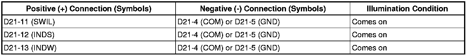
(c) Check if the illumination for the engine switch comes on.
OK:
NG -- REPLACE ENGINE SWITCH
OK -- Continue to next step.
2. CHECK WIRE HARNESS (ENGINE SWITCH - POWER SOURCE CONTROL ECU AND BODY GROUND)
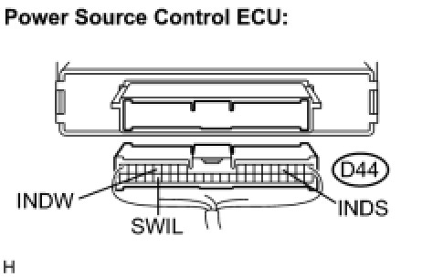
(a) Disconnect the D44 ECU connector.
(b) Measure the resistance according to the value(s) in the table below.
Resistance:
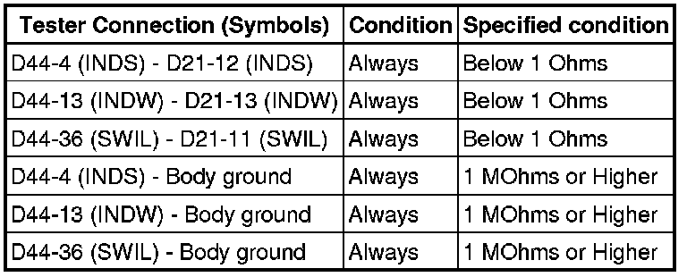
NG -- REPAIR OR REPLACE HARNESS OR CONNECTOR
OK -- REPLACE POWER SOURCE CONTROL ECU