System Specifications
CYLINDER HEAD SUB-ASSEMBLY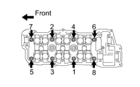
Using several steps, install and tighten the 8 cylinder head bolts uniformly in the sequence shown in the illustration.
Torque 54 Nm (550 kgf-cm, 40 ft-lbf)
The cylinder head bolts are tightened in 2 successive steps.
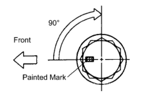
Mark the front side of each cylinder head bolt head with paint as shown in the illustration.
Retighten the cylinder head bolts by 90° in the same sequence as step .
Check that each painted mark is now at a 90° angle to the front.
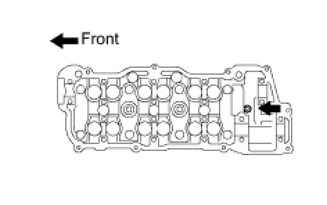
Using an 8 mm socket hexagon wrench, install the hexagon bolt.
Torque 19 Nm (194 kgf-cm, 14 ft-lbf)
CYLINDER HEAD LH
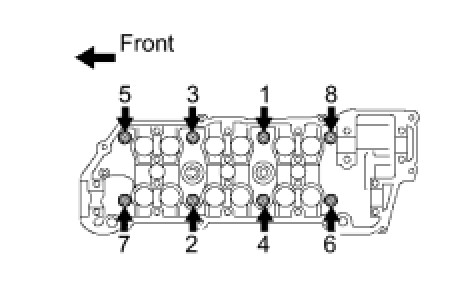
Using several steps, install and tighten the 8 cylinder head bolts uniformly in the sequence shown in the illustration.
Torque 54 Nm (551 kgf-cm, 40 ft-lbf)
The cylinder head bolts are tightened in 2 successive steps.
Mark the front side of each cylinder head bolt head with paint as shown in the illustration.
Retighten the cylinder head bolts by 90° in the same sequence as step.
Check that each painted mark is now at a 90° angle to the front.
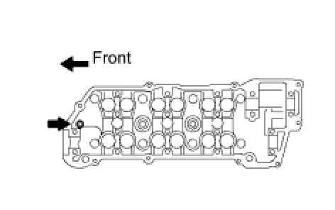
Using an 8 mm socket hexagon wrench, install the hexagon bolt.
Torque 19 Nm (189 kgf-cm, 14 ft-lbf)
CYLINDER HEAD SET BOLT
Standard Outside Diameter 8.95 to 9.05 mm (0.3524 to 0.3563 in.)
Minimum Outside Diameter 8.75 mm (0.3445 in.)
If the diameter is less than the minimum, replace the bolt
CYLINDER HEAD WARPAGE

INTAKE MANIFOLD
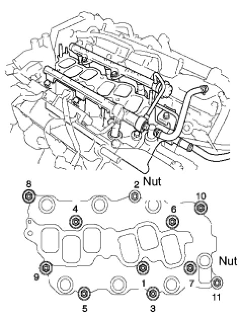
Install the intake manifold with the 9 bolts, 2 nuts and 2 washers. Using several steps, tighten the bolts and nuts uniformly in the sequence shown in the illustration.
Torque 15 Nm (153 kgf-cm, 11 ft-lbf)
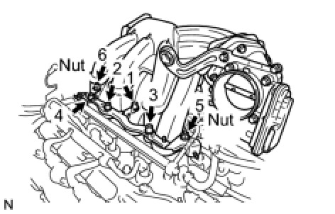
(b) Using a socket hexagon wrench 8 mm, install the intake air surge tank with the 4 bolts and 2 nuts. Using several steps, tighten the bolts and nuts uniformly in the sequence shown in the illustration.
Torque: 28 Nm (286 kgf-cm, 21 ft-lbf)
NO. 2 CAMSHAFT
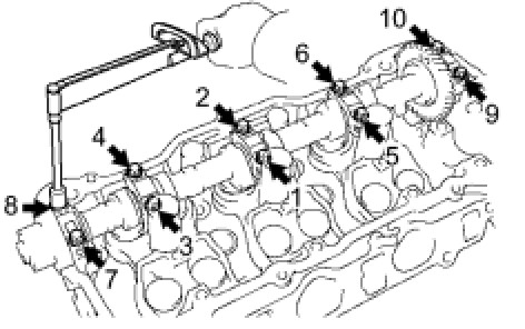
Using several steps, tighten the 10 bearing cap bolts uniformly in the sequence shown in the illustration.
Torque 16 Nm (163 kgf-cm, 12 ft-lbf)
CAMSHAFT
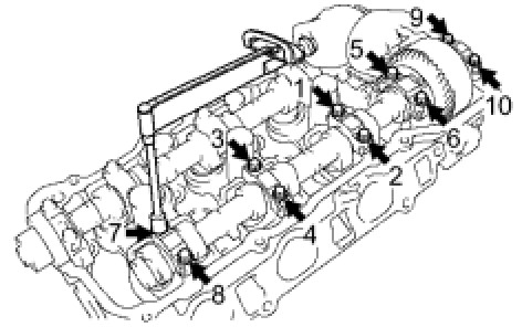
Using several steps, tighten the 10 bearing cap bolts uniformly in the sequence shown in the illustration.
Torque 16 Nm (163 kgf-cm, 12 ft-lbf)
NO. 4 CAMSHAFT SUB-ASSEMBLY
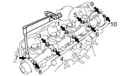
Using several steps, tighten the 10 bearing cap bolts uniformly in the sequence shown in the illustration.
Torque 16 Nm (163 kgf-cm, 12 ft-lbf)
NO. 3 CAMSHAFT SUB-ASSEMBLY
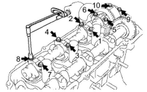
Using several steps, tighten the 10 bearing cap bolts uniformly in the sequence shown in the illustration.
Torque 16 Nm (163 kgf-cm, 12 ft-lbf)
CAMSHAFT TIMING GEAR ASSEMBLY
Torque 150 Nm (1530 kgf-cm, 111 ft-lbf)
EXHAUST MANIFOLD SUB-ASSEMBLY RH
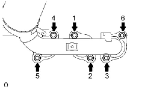
Install a new gasket and the exhaust manifold RH with the 6 nuts. Using several steps, tighten the nuts uniformly in the sequence shown in the illustration.
Torque 49 Nm (500 kgf-cm, 36 ft-lbf)