System Main Relay
P112 HYBRID BATTERY CONTROL: SYSTEM MAIN RELAY: INSPECTION
INSPECTION
1. INSPECT NO. 1 SYSTEM MAIN RELAY
NOTE: Connectors B and C have the same shape. Identify each connector by the wire harness length (L) and the wire harness color on the terminal 2 side.

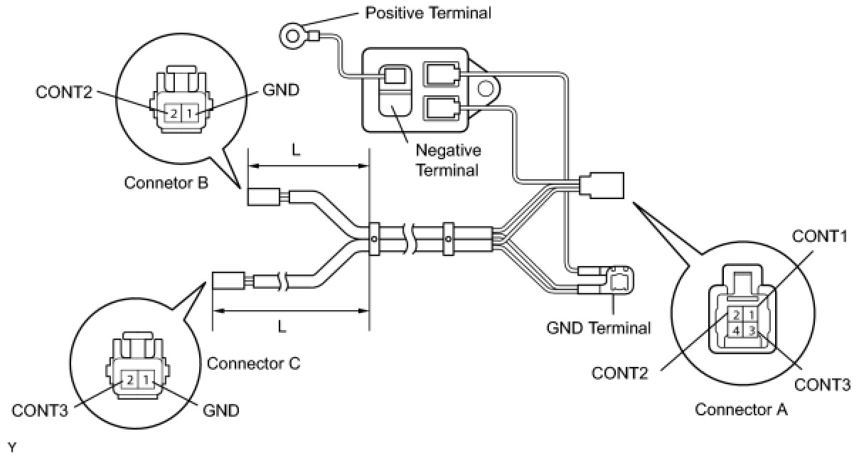
(a) Check the resistance.
(1) Measure the resistance between the connectors.
Standard resistance:
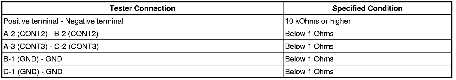
If the results are not as specified, replace the No. 1 system main relay.
(2) Apply battery voltage between the GND terminal and CONT1 terminal of the connector A, then measure the resistance between the positive and negative terminals.
Standard resistance:
Below 1 Ohms
If the results are not as specified, replace the No. 1 system main relay.
(b) Inspect the resistance.
(1) Measure the resistance between the GND terminal and CONT1 terminal of the connector A.
Standard resistance:
70 to 160 kOhms
If the the results are not as specified, replace the No. 1 system main relay.
2. INSPECT NO. 2 SYSTEM MAIN RELAY
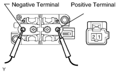
(a) Install the 2 installed nuts to the negative and positive terminals.
Torque: 5.6 Nm (57 kgf-cm, 50 in-lbf)
(b) Check the resistance.
(1) Measure the resistance between the positive and negative terminals.
Standard resistance:
10 kOhms or higher
If the result is not as specified, replace the No. 2 system main relay.
(2) Apply battery voltage between the connector terminals, then measure the resistance between the positive and negative terminals.
Standard resistance:
Below 1 Ohms
If the result is not as specified, replace the No. 2 system main relay.
(c) Inspect the resistance.
(1) Measure the resistance between the connector terminals.
Standard resistance:
20 to 50 kOhms
If the result is not as specified, replace the No. 2 system main relay.
3. INSPECT NO. 3 SYSTEM MAIN RELAY
(a) Install the 2 installed nuts to the negative and positive terminals.
Torque: 5.6 Nm (57 kgf-cm, 50 in-lbf)
(b) Check the resistance.
(1) Measure the resistance between the positive and negative terminals.
Standard resistance:
10 kOhms or higher
If the result is not as specified, replace the No. 3 system main relay.
(2) Apply battery voltage between the connector terminals, then measure the resistance between the positive and negative terminals.
Standard resistance:
Below 1 Ohms
If the result is not as specified, replace the No. 3 system main relay.
(c) Inspect the resistance.
(1) Measure the resistance between the connector terminals.
Standard resistance:
20 to 50 kOhms
If the result is not as specified, replace the No. 3 system main relay.