Part 2
U241E AUTOMATIC TRANSAXLE: AUTOMATIC TRANSAXLE UNIT: REASSEMBLY
Part 2 of 3
Continued From Part 1 Part 1
18. INSTALL NO. 1 GOVERNOR APPLY GASKET
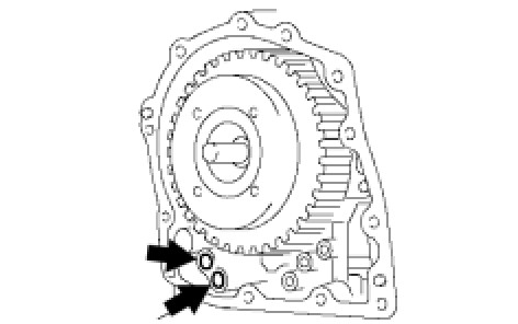
(a) Install 2 new apply gaskets to the transaxle.
19. INSTALL FRONT CLUTCH APPLY TUBE
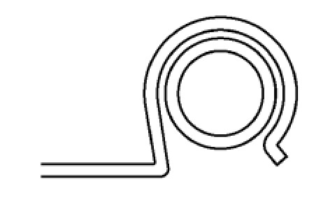
(a) Install the clamp to the front clutch apply tube.
NOTE: Make sure to install the clamp to the apply pipe before installing the apply pipe to the transaxle case. This prevents the apply pipe from being deformed or damaged.
20. INSTALL BRAKE APPLY TUBE
(a) Install the clamp to the brake apply tube.
NOTE: Make sure to install the clamp to the apply pipe before installing the apply pipe to the transaxle case. This prevents the apply pipe from being deformed or damaged.
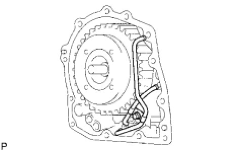
(b) Install the 2 apply tubes to the transaxle with the bolt.
Torque: 5.4 Nm (55 kgf-cm, 48 in-lbf)
NOTE: Each pipe should be securely inserted until it reaches the stopper.
21. INSTALL NO. 1 TRANSAXLE CASE PLUG
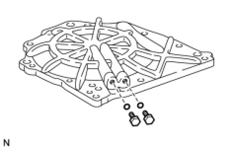
(a) Install 2 new O-rings to the 2 plugs.
(b) Install the 2 plugs to the transaxle rear cover.
Torque: 7.4 Nm (75 kgf-cm, 65 in-lbf)
22. INSTALL TRANSAXLE REAR COVER SUB-ASSEMBLY
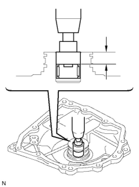
(a) Using SST and a press, press in the bearing.
SST: 09950-60010
09951-00230
09951-00350
Standard depth:
12.05 to 12.75 mm (0.4744 to 0.5020 in.)
NOTICE:
- Face the inscribed mark side of the bearing race up.
- Repeat the press-fit until the specified value is obtained.
(b) Apply adhesive to the 2 screws.
Adhesive:
Toyota Genuine Adhesive 1344, Three Bond 1344 or equivalent
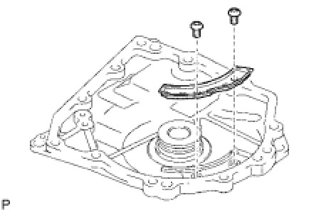
(c) Using a T30 ''TORX'' socket, install the transaxle rear cover plate with the 2 screws.
Torque: 7.5 Nm (76 kgf-cm, 66 in-lbf)
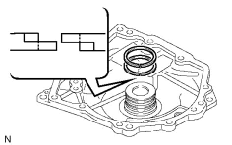
(d) Coat 2 new oil seal rings with ATF, and install them to the transaxle rear cover.
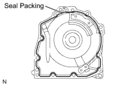
(e) Remove any packing material and be careful not to get oil on the contacting surfaces of the transaxle rear cover or the transaxle.
(f) Apply seal packing to the cover.
Seal packing:
Toyota Genuine Seal Packing 1281, Three Bond 1281 or equivalent
(g) Coat the needle roller bearing with ATF.
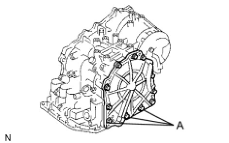
(h) Apply adhesive to the threads of the bolts labeled A.
Adhesive:
Toyota Genuine Adhesive 1344, Three Bond 1344 or equivalent
(i) Install the 11 bolts.
Torque: 19 Nm (194 kgf-cm, 14 ft-lbf) for bolt A
Torque: 25 Nm (255 kgf-cm, 18 ft-lbf) for other bolt
23. INSTALL UNDERDRIVE CLUTCH DRUM OIL SEAL RING
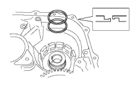
(a) Install 2 new oil seals to the transaxle.
24. INSTALL UNDERDRIVE BRAKE PISTON
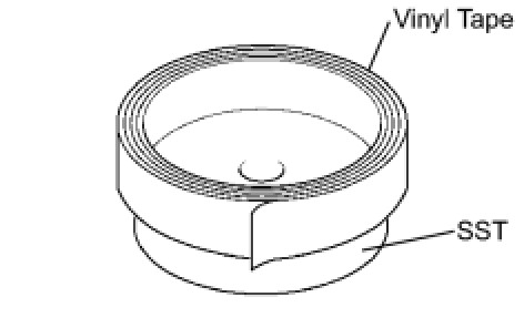
(a) Wind a vinyl tape around SST at the 4.0 mm (0.157 in.) above from the bottom end until the thickness of the wound tape is about 5.0 mm (0.197 in.).
SST: 09550-60010
09951-00320
NOTE: Clean SST to remove deposited oil before winding a vinyl tape.
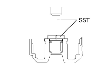
(b) Using SST and a press, press in the needle-roller bearing to the transaxle until the wound vinyl tape contacts the transaxle case.
SST: 09550-60010
09951-00320
SST: 09950-70010
09951-07100
SST: 09387-00020
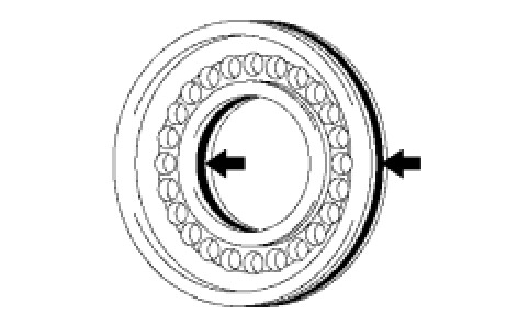
(c) Coat 2 new O-rings with ATF, and install them to the underdrive brake piston.
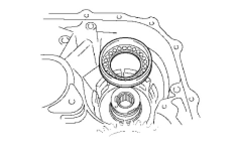
(d) Install the underdrive brake piston to the transaxle.
25. INSTALL UNDERDRIVE BRAKE RETURN SPRING SUB-ASSEMBLY
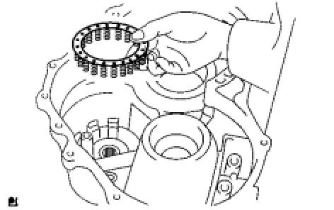
(a) Install the underdrive brake return spring to the underdrive brake piston.
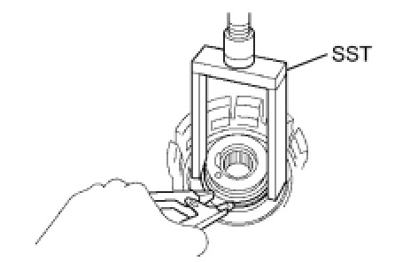
(b) Using SST, a snap ring expander and press, press the return spring and install the snap ring to the transaxle.
SST: 09387-00020
NOTE: Do not apply excessive pressure.
26. INSTALL NO. 2 UNDERDRIVE CLUTCH DISC
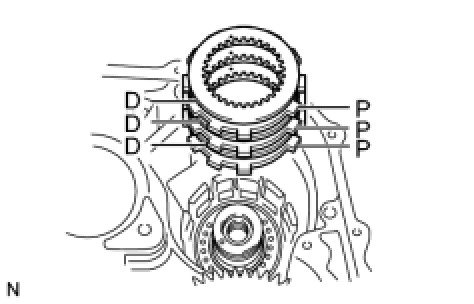
(a) Install the 3 discs and 3 plates to the transaxle.
Install in order:
P - D - P - D - P - D
HINT: D = Disc
P = Plate
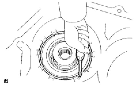
(b) Using a screwdriver, install the snap ring.
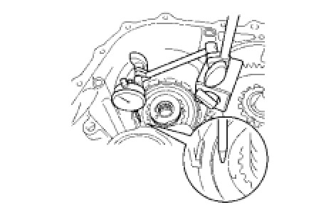
(c) Using a dial indicator, measure the underdrive brake piston stroke while applying and releasing compressed air (392 kPa, 4.0 kgf/cm2, 57 psi).
Standard piston stroke:
1.81 to 2.20 mm (0.0713 to 0.0866 in.)
HINT: Select an appropriate flange from the table below so that it will meet the specified value.
Standard flange thickness:
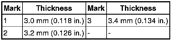
(d) Temporarily remove the snap ring and attach the flange. Restore the snap ring.
27. INSTALL UNDERDRIVE 1-WAY CLUTCH ASSEMBLY
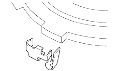
(a) Install the outer race retainer to the 1-way clutch.
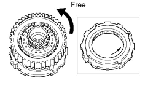
(b) Install the underdrive clutch assembly to the 1-way clutch. Rotate the underdrive clutch to check the rotating direction for the lock or free operation.
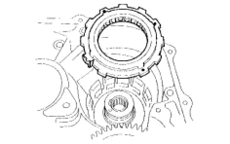
(c) Install the 1-way clutch to the transaxle.
NOTE: Make sure that the mark on the 1-way clutch outer race is visible.
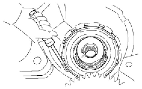
(d) Using a screwdriver, install the snap ring to the transaxle.
28. INSTALL UNDERDRIVE CLUTCH
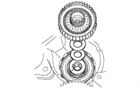
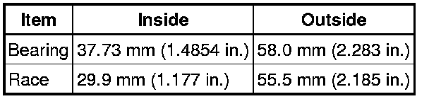
(a) Coat the bearing and bearing race with petroleum jelly, and install them onto the underdrive clutch.
Standard race diameter:
(b) Install the underdrive clutch assembly to the transaxle.
29. INSTALL UNDERDRIVE PLANETARY GEAR ASSEMBLY
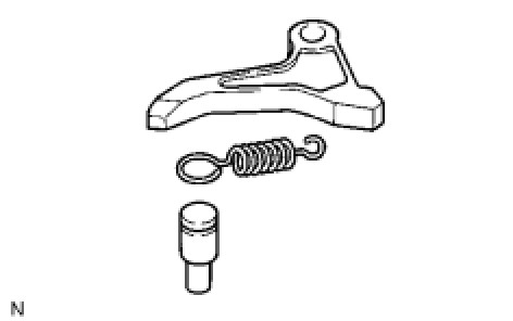
(a) Install the parking lock pawl pin and torsion spring to the parking lock pawl.
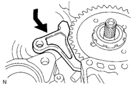
(b) Temporarily install the parking lock pawl, shaft and spring to the transaxle case as shown in the illustration.
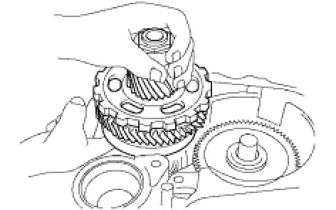
(c) Install the underdrive planetary gear assembly to the transaxle.
NOTE: Engage all the discs of the underdrive clutch and hub splines of the underdrive planetary gear assembly firmly and assemble them securely.
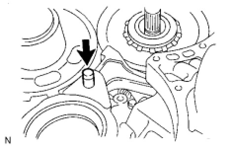
(d) Install the parking lock pawl shaft.
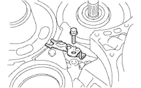
(e) Install the pawl shaft clamp with the bolt.
Torque: 9.8 Nm (100 kgf-cm, 87 in-lbf)
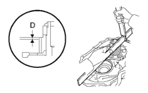
(f) Using a straightedge and vernier caliper as shown in the illustration, measure the gap between the top of the differential drive pinion in the underdrive planetary gear and contact surface of the transaxle and housing (Dimension D).
NOTE: Note down the dimension D as it is necessary for the following process.
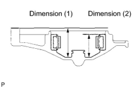
(g) As shown in the illustration, measure the 2 places of the transaxle housing. Calculate the dimension E using the formula.
NOTE: Note down the dimension E as it is necessary for the following process.
HINT: Dimension E = Dimension (1) - Dimension (2)
30. INSPECT MULTIPLE DISC CLUTCH CLUTCH HUB Transaxle Unit
31. INSTALL MULTIPLE DISC CLUTCH CLUTCH HUB
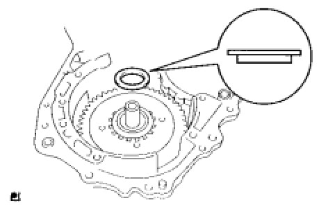
(a) Install the bearing race to the transaxle while checking its direction.
Standard bearing diameter:

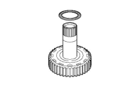
(b) Coat the thrust needle roller bearing and race with petroleum jelly, and install them onto the multiple disc clutch hub.
Standard thrust bearing and race diameter:

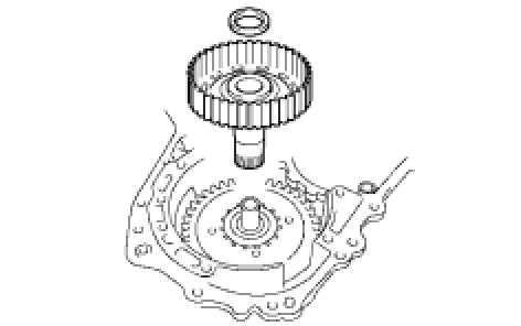
(c) Install the input shaft thrust bearing to the multiple clutch hub.
Standard bearing diameter:

(d) Install the forward clutch hub to the transaxle.
32. INSTALL FORWARD CLUTCH ASSEMBLY
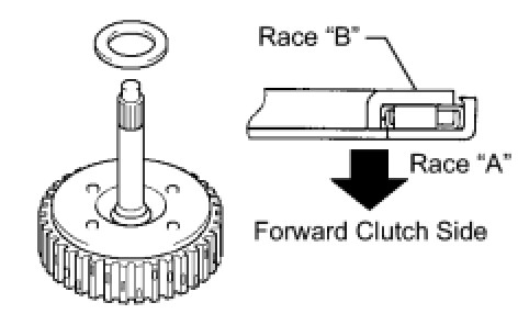
(a) Install the input shaft thrust bearing to the forward clutch.
Standard bearing diameter:

NOTE: Install the thrust bearing properly so that the race "B" will be visible.
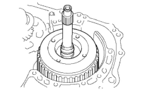
(b) Install the forward clutch to the multiple clutch hub.
NOTE: Align the splines of all discs in the forward clutch with those of multiple clutch hub to assemble them securely.
33. INSTALL OVERDRIVE BRAKE GASKET
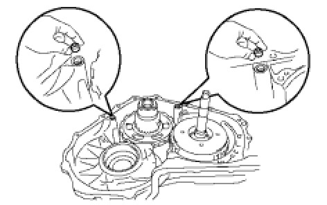
(a) Install 2 new overdrive brake gaskets to the transaxle.
34. INSTALL FRONT DIFFERENTIAL ASSEMBLY
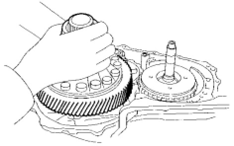
(a) Install the differential assembly to the transaxle.
Continued in Part 3 Part 3