Part 3
U241E AUTOMATIC TRANSAXLE: AUTOMATIC TRANSAXLE UNIT: REASSEMBLY - (Continued)
Part 3 of 3
Continued From Part 2 Part 2
REASSEMBLY
35. INSTALL NO. 2 THRUST BEARING UNDERDRIVE RACE
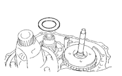
(a) Install the thrust bearing race to the underdrive planetary gear.
36. INSTALL THRUST NEEDLE ROLLER BEARING
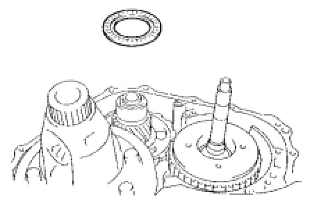
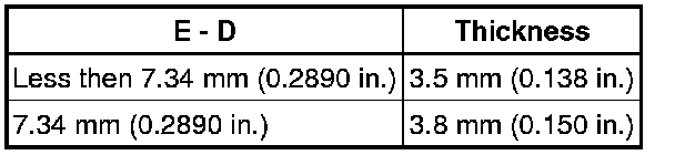
(a) Calculate the end play value using the following formula and value of Dimensions D and E that were measured when installing the cylindrical roller bearing and underdrive planetary gear. Select an appropriate underdrive planetary gear thrust bearing race No. 2 which satisfies the specified end play value, and install it.
Standard end play:
0.498 to 0.993 mm (0.0194 to 0.0390 in.)
HINT: End play = Dimension E - Dimension D - thrust bearing thickness 3.28 mm (0.1291 in.) - underdrive thrust bearing race thickness.
Standard race thickness:
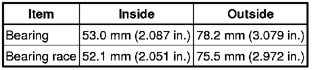
Standard bearing and bearing race diameter
37. INSTALL OIL PUMP ASSEMBLY
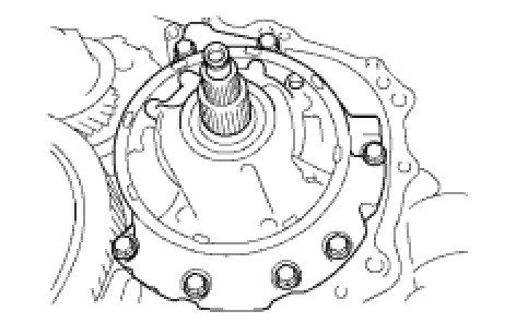
(a) Install the oil pump to the transaxle with the 7 bolts.
Torque: 22 Nm (226 kgf-cm, 16 ft-lbf)
38. INSTALL UNDERDRIVE OUTPUT SHAFT OIL SEAL RING
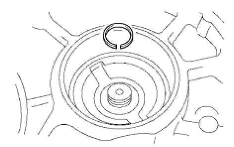
(a) Install a new oil seal ring to the transaxle housing.
39. INSTALL UNDERDRIVE CYLINDRICAL ROLLER BEARING
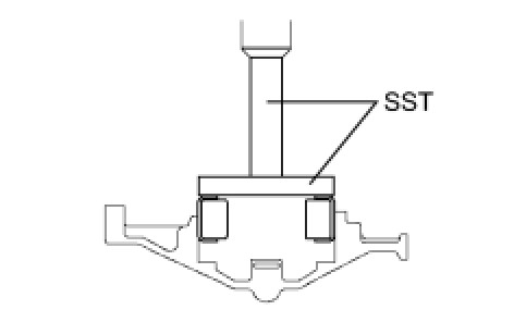
(a) Using SST and a press, press in the underdrive cylindrical roller bearing.
SST: 09950-60020
SST: 09950-70010
09951-07100
09951-07100
NOTE: Do not apply excessive pressure to it.
40. INSTALL TRANSAXLE HOUSING
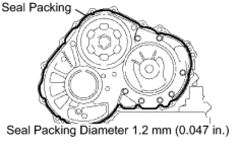
(a) Remove any packing material and be careful not to get oil on the contacting surfaces of the transaxle case or transaxle housing.
(b) Apply seal packing to the transaxle case.
Seal packing:
Toyota Genuine Seal Packing 1281, Three Bond 1281 or equivalent
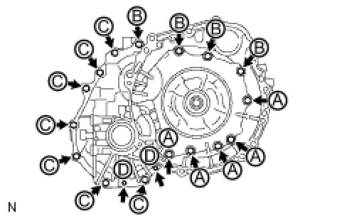
(c) Install the transaxle housing and to the transaxle with the 18 bolts.
Torque: 22 Nm (224 kgf-cm, 16 ft-lbf)
Torque: 29 Nm (296 kgf-cm, 21 ft-lbf)
Torque: 10 Nm (102 kgf-cm, 7 ft-lbf)
HINT: Each bolt length is indicated below.
Bolt length:
50 mm (1.969 in.) for bolt A, B and D
42 mm (1.654 in.) for bolt C
NOTE: Because the bolt A is a seal bolt, apply the seal packing to new bolts and tighten them within 10 minutes after application.
Seal packing:
Toyota Genuine Seal Packing 1281, Three Bond 1281 or equivalent
41. INSTALL NO. 1 TRANSAXLE CASE PLUG
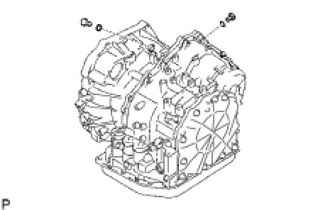
(a) Install 2 new O-rings to the 2 plugs.
(b) Install the 2 plugs to the transaxle housing.
Torque: 7.4 Nm (75 kgf-cm, 65 in-lbf)
42. INSPECT INPUT SHAFT END PLAY Transaxle Unit
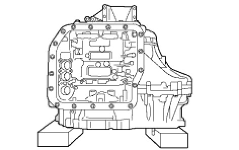
43. FIX AUTOMATIC TRANSAXLE ASSEMBLY
44. INSTALL MANUAL VALVE LEVER SHAFT OIL SEAL
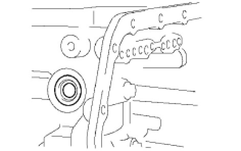
(a) Coat a new oil seal with ATF, and install it to the transaxle.
(b) Install the oil seal to the transaxle.
45. INSTALL PARKING LOCK ROD SUB-ASSEMBLY
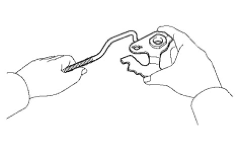
(a) Install the parking lock rod to the manual valve lever.
46. INSTALL MANUAL VALVE LEVER SUB-ASSEMBLY
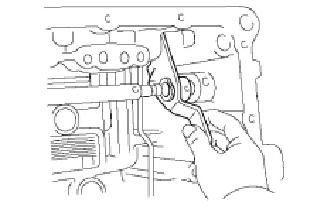
(a) Install a new spacer and manual valve lever shaft to the transaxle.
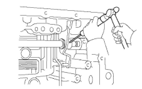
(b) Using a pin punch and hammer, tap in a new pin.
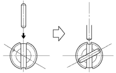
(c) Turn the spacer and lever shaft to align the small hole for locating the staking position in the spacer with the staking position mark on the lever shaft.
(d) Using a pin punch, stake the spacer through the small hole.
(e) Check that the spacer does not turn.
47. INSTALL MANUAL VALVE LEVER SHAFT RETAINER SPRING
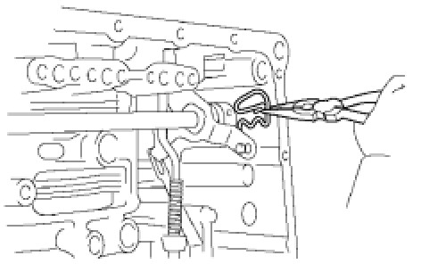
(a) Using needle-nose pliers, install the retainer spring.
48. INSTALL PARKING LOCK PAWL BRACKET
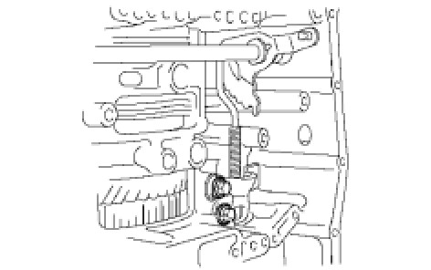
(a) Install the parking lock pawl bracket with the 2 bolts.
Torque: 20 Nm (204 kgf-cm, 15 ft-lbf)
Bolt length:
25 mm (0.984 in.)
49. INSTALL MANUAL DETENT SPRING SUB-ASSEMBLY
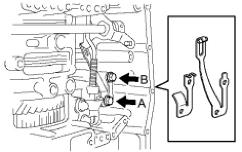
(a) Install the manual detent spring with the 2 bolts.
NOTE: Make sure to install the manual detent spring and cover in this order.
Torque: 20 Nm (204 kgf-cm, 15 ft-lbf)
Torque: 12 Nm (122 kgf-cm, 9 ft-lbf)
HINT: Each bolt length is indicated below.
Bolt length:
27 mm (1.063 in.) for bolt A
16 mm (0.630 in.) for bolt B
50. INSTALL B-3 ACCUMULATOR PISTON
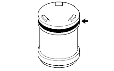
(a) Coat a new O-ring with ATF, and install it to the B-3 accumulator piston.
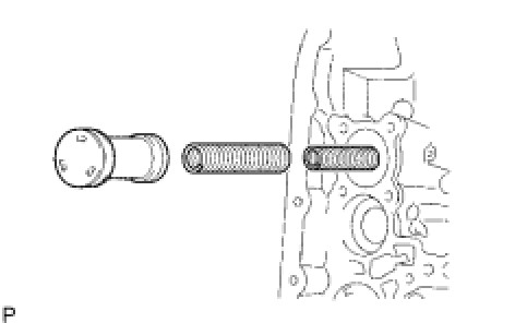
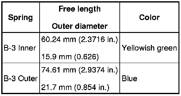
(b) Coat the accumulator B-3 piston and spring with ATF, and install them to the transaxle.
Standard accumulator spring:
51. INSTALL C-1 ACCUMULATOR PISTON
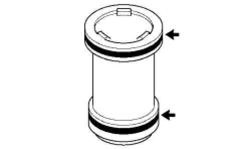
(a) Coat 2 new O-rings with ATF, and install them to the C-1 accumulator piston.
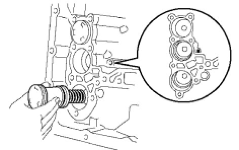
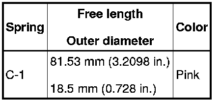
(b) Coat the accumulator C-1 piston with ATF, and install it to the transaxle.
Standard accumulator spring:
52. INSTALL C-3 ACCUMULATOR PISTON
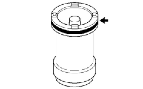
(a) Coat a new O-ring with ATF, and install it to the C-3 accumulator piston.
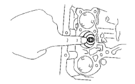
(b) Coat the C-3 accumulator piston with ATF, and install it to the transaxle.
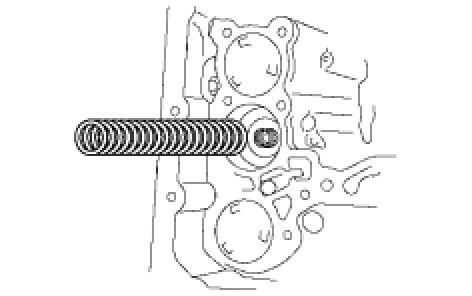
(c) Install the compression spring from the C-3 accumulator piston.
53. INSTALL CHECK BALL BODY
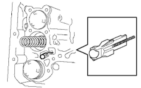
(a) Install the check ball body and spring.
54. INSTALL TRANSMISSION WIRE
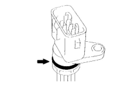
(a) Coat a new O-ring with ATF, and install it to the transaxle solenoid wire.
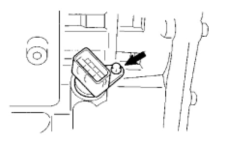
(b) Install the solenoid wire retaining bolt.
Torque: 5.4 Nm (55 kgf-cm, 48 in-lbf)
55. INSTALL BRAKE DRUM GASKET
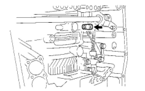
(a) Coat a new brake drum gasket with ATF, and install it to the transaxle.
56. INSTALL TRANSAXLE CASE 2ND BRAKE GASKET
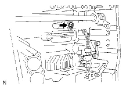
(a) Coat a new transaxle case 2nd brake gasket with ATF, and install it to the transaxle.
57. INSTALL NO. 1 GOVERNOR APPLY GASKET
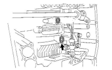
(a) Coat a new governor apply gasket No. 1 with ATF, and install it to the transaxle.
58. INSTALL TRANSMISSION VALVE BODY ASSEMBLY
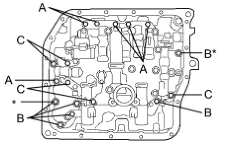
(a) Make sure that the manual valve lever position, install the valve body with the 17 bolts to the transaxle.
Torque: 11 Nm (112 kgf-cm, 8 ft-lbf)
HINT: Each bolt length is indicated below.
Bolt length:
25 mm (0.984 in.) for bolt A
41 mm (1.614 in.) for bolt B
45 mm (1.771 in.) for bolt C
NOTICE:
- Push the valve body against the accumulator piston spring and the check ball body to install it.
- When installing the valve body to the transaxle case, do not hold the solenoids.
- Tighten the bolts marked by * in the illustration first temporarily because they are positioning bolts.
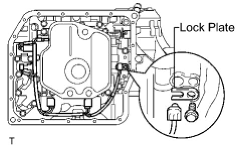
(b) Connect the 5 solenoid connectors.
(c) Install the ATF temperature sensor, clamp and bolt.
Torque: 6.6 Nm (67 kgf-cm, 58 in-lbf)
59. INSTALL VALVE BODY OIL STRAINER ASSEMBLY
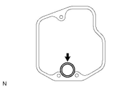
(a) Coat a new O-ring with ATF, and install it to the oil strainer.
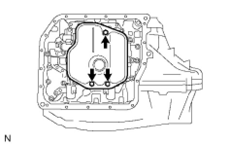
(b) Install the oil strainer and 3 bolts to the valve body.
Torque: 11 Nm (112 kgf-cm, 8 ft-lbf)
60. INSTALL AUTOMATIC TRANSAXLE OIL PAN SUB-ASSEMBLY
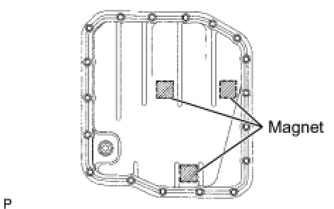
(a) Install the 3 magnets in the oil pan.
(b) Install a new oil pan gasket to the oil pan.
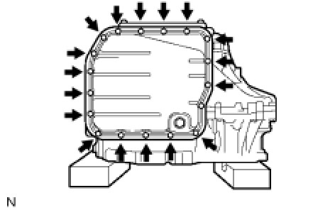
(c) Install the oil pan to the transaxle with the 18 bolts.
Torque: 7.6 Nm (77 kgf-cm, 67 in-lbf)
NOTE: Because the bolts are seal bolts, apply seal packing to new bolts and tighten them within 10 minutes after application.
61. INSTALL SPEED SENSOR
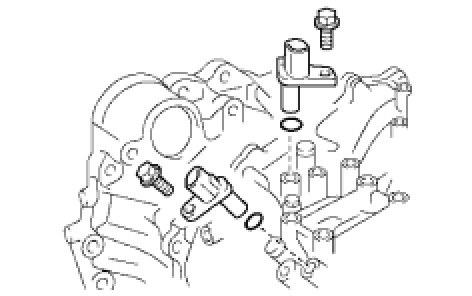
(a) Coat 2 new O-rings with ATF, and install them to the 2 sensors.
(b) Install the 2 sensors with the 2 bolts to the transaxle.
Torque: 11 Nm (112 kgf-cm, 8 ft-lbf)
62. INSTALL OIL COOLER INLET TUBE UNION
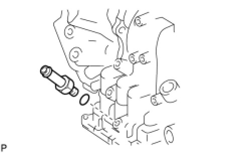
(a) Coat a new O-ring with ATF, and install it to the union.
(b) Install the union to the transaxle.
Torque: 27 Nm (276 kgf-cm, 20 ft-lbf)
63. INSTALL OIL COOLER OUTLET TUBE UNION
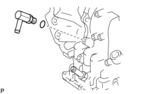
(a) Coat a new O-ring with ATF, and install it to the union.
(b) Install the union to the transaxle case.
Torque: 25 Nm (255 kgf-cm, 18 ft-lbf)
64. INSTALL NO. 1 TRANSAXLE CASE PLUG
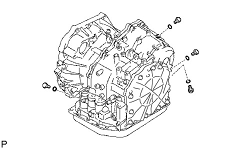
(a) Coat 4 new O-rings with ATF, and install them to the 4 plugs.
(b) Install the 4 plugs to the transaxle.
Torque: 7.4 Nm (75 kgf-cm, 65 in-lbf)
65. INSTALL BREATHER PLUG HOSE
(a) Install the breather plug hose to the breather plug.
66. INSTALL PARK/NEUTRAL POSITION SWITCH ASSEMBLY
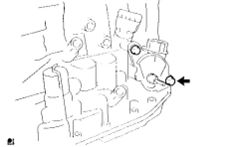
(a) Install the park/neutral position switch onto the manual valve lever shaft and temporarily install the 2 adjusting bolts.
(b) Install a new lock plate and the nut.
Torque: 5.4 Nm (55 kgf-cm, 48 in-lbf)
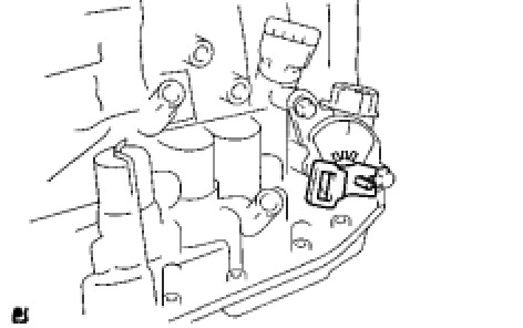
(c) Temporarily install the control shaft lever.
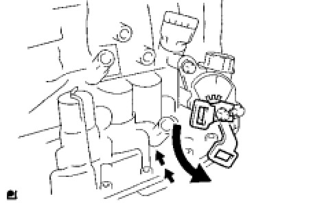
(d) Turn the lever counterclockwise until it stops, and then turn it clockwise 2 notches.
(e) Remove the control shaft lever.
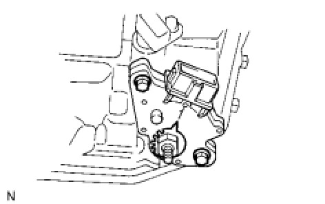
(f) Align the groove with neutral basic line.
(g) Tighten the 2 bolts.
Torque: 6.9 Nm (70 kgf-cm, 61 in-lbf)
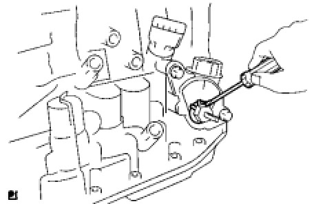
(h) Using a screwdriver, stake the nut with the lock plate.
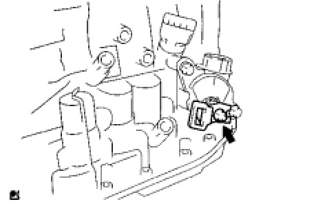
(i) Install the control shaft lever, washer and nut.
Torque: 13 Nm (133 kgf-cm, 10 ft-lbf)
67. INSTALL SPEEDOMETER DRIVEN HOLE COVER SUB-ASSEMBLY
(a) Coat a new O-ring with ATF and install it to the hole cover.
(b) Install the hole cover to the transaxle with the bolt.